Hydraulic Central Manifolds Manufacturer

  • Compact integration reduces leakage points and service time; 
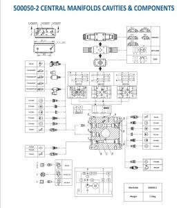
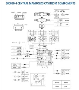
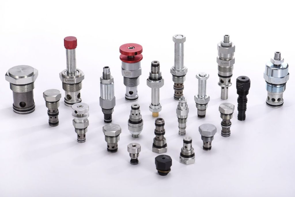
  • Modular cartridge cavities (08/10 size) enable flexible circuits: raise, hold, controlled lowering.
  • Compatible with 12/24V DC micro HPUs and AC units; supports common SAE/BSPP ports.
  • Material options: 6061‑T6 aluminum (lightweight, thermal), die‑cast aluminum (cost‑effective).
OUR PRODUCT

Hydraulic Central Manifold Configurations

Aluminum Hydraulic Central Manifold

Aluminum Hydraulic Central Manifold

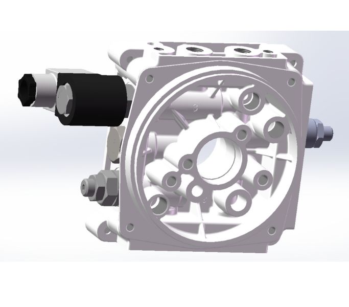
An aluminum hydraulic central manifold offers lightweight strength and excellent heat dissipation for compact power units. Typical specs include 6061‑T6 construction, 5–25 L/min flow, up to 210 bar working pressure, SAE 6/8 ports, and an anodized finish. Ideal for mobile equipment, lift tables, and DC HPU platforms requiring efficient flow paths and reduced weight.
Die-cast Hydraulic Central Manifold

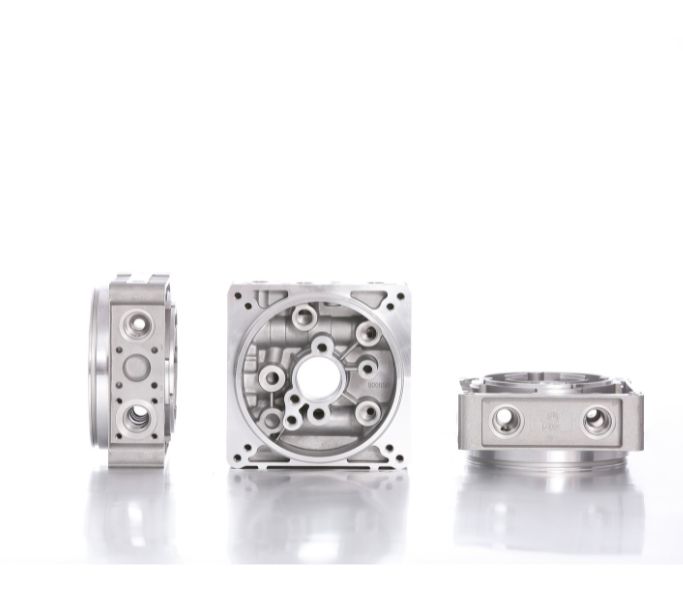
Die-cast Hydraulic Central Manifold

Die‑cast hydraulic central manifolds deliver cost‑effective, repeatable performance for high‑volume OEM power packs. Common parameters: 5–20 L/min, 160–250 bar, BSPP/SAE threaded ports, integrated relief/check/flow control cavities. Perfect for pallet trucks, scissor lifts, and dock levelers where compact form factor and robust casting meet reliable circuit integration.

DC Power Pack Central Manifold

DC Power Pack Central Manifold

Designed for 12/24V DC power packs, the central manifold integrates raising, lowering, hold, relief, check, and down‑speed/flow control functions. Typical specs: 0.8–2.5 ml/rev pumps, 16–25 MPa system pressure, 5–15 L/min flow, cartridge cavities 08/10 size. Widely used in lift tables, tail lifts, tippers, RV leveling, and compact mobile hydraulics.
Hydraulic Power Unit Central Manifold

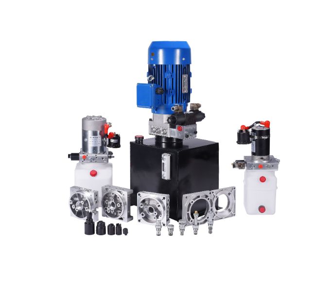
Hydraulic Power Unit Central Manifold

The HPU central manifold is the core distribution block for AC/DC units, optimizing pressure drop and simplifying service. Typical specs: 10–30 L/min, 160–315 bar, SAE/BSPP ports, modular cartridge circuits (raise/lower/hold) and optional test ports. Applications include industrial machinery, mobile equipment, and marine systems with consistent, clean control.
Custom Hydraulic Central Manifolds

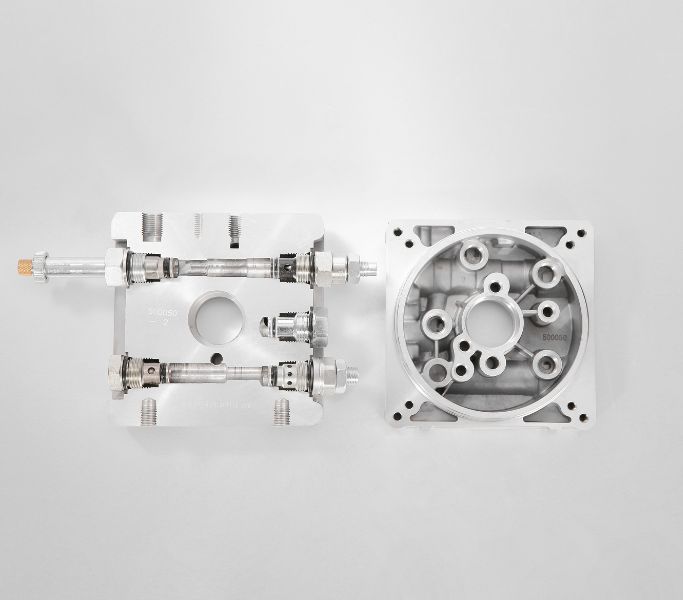
Custom Hydraulic Central Manifolds

Custom hydraulic central manifolds are engineered to your circuit, footprint, and material needs. Typical ranges: 5–40 L/min, 160–315 bar, SAE/BSPP/CETOP interfaces, aluminum or steel, anodized or black oxide. Tailored cavities and channels reduce pressure loss and assembly time—ideal for OEM HPUs and multi‑function systems needing compact, integrated control.
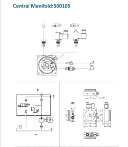
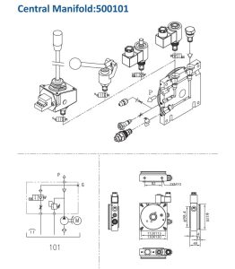
Hydraulic Central Manifold Circuit and Interface Review

Hydrath designs and manufactures Hydraulic Central Manifolds that connect the motor, gear pump, and tank in compact AC/DC hydraulic power units.

Our central manifold blocks integrate single‑acting and double‑acting circuits for raise, hold, and controlled lowering, while reducing hose runs and pressure drop.

Consequently, your system becomes more efficient, easier to service, and truly reliable.

ParameterSpecification
Product NameHydraulic Central Manifold
Working MediumHydraulic oil
Circuit TypesSingle Acting / Double Acting
Operating PressureUp to 250 bar (≈3625 PSI)
Relief Setting Range40–315 bar
Max Flow0–28 LPM
Cartridge CavitiesSize 8 (3/4″–16 UNF, 08‑2) / Size 10 (10‑2)
Port Threads3/8″ BSPP (standard); 1/4″ BSPP optional; BSPP/NPT/SAE/Metric customizable
Number of PortsStandard or custom (varies by design)
Materials6061‑T6 extruded aluminum; ADC12/A380 die‑cast aluminum; steel optional
Surface FinishAnodized / Zinc‑plated / Black oxide (optional)
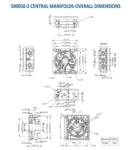
Mounting Interface2 × M10 threads, 82 mm centers
Working Temperature−35°C to +120°C (typical); −30°C to +105°C (variant)
Compatible Power UnitsDC 12/24V; AC single‑phase / three‑phase
Expansion OptionsCETOP 03 stackable valves; test/bypass ports

Hydraulic Central Manifolds integrate core raise/lower/hold, relief, check, and down‑speed control into a compact block, minimizing hose runs and pressure loss for AC/DC power units. They support micro power packs and OEM HPUs across lift tables, pallet trucks, dock levelers, and tail lifts.

Hydraulic Central Manifolds Design

  • 2D/3D CAD: UG/SolidWorks for manifold modeling and circuit layout
  • Industry Common Cavities: Size 8 (3/4″–16 UNF, 08‑2), Size 10 (10‑2)
  • Circuit Types: Single/Double acting; integrated relief (40–315 bar), check, flow control (down‑speed), solenoid lowering (NC/NO) or manual lowering
  • Ports: Standard 3/8″ BSPP (optional 1/4″ BSPP); BSPP/NPT/SAE/Metric customizable
  • Materials: 6061‑T6 extruded aluminum; ADC12/A380 die‑cast aluminum; steel available
  • Mounting: 2 × M10 threads, 82 mm centers; CETOP 03 stack manifold interface optional
  • Customization: Port location/size, circuit design, number of ports, logo/marking
Hydraulic Central Manifolds Design​
Hydraulic Central Manifolds Machining​

Hydraulic Central Manifolds Machining

  • Raw Stock Cutting: Square long aluminum bars and round manifold stock; multiple large cutting machines; 24/7 cutting
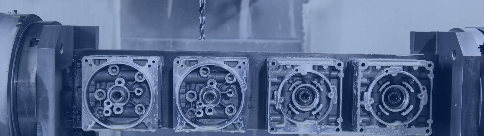
  • CNC Machining: >20 large 4‑axis CNCs with tool magazines; 3 shifts, 24 hours/day; computer programming and CAM workflows
  • Process Range: Extruded and die‑cast aluminum machining; steel machining; deburring, channel optimization; anodizing/zinc/black oxide finishes
  • Volume Flexibility: Standard and custom designs; no MOQ for standard models

Hydraulic Central Manifolds Testing Capabilities

  • Pressure & Leak: Hydrostatic pressure and leak tests up to 250 bar; aluminum center blocks recommended for continuous ≤210 bar
  • Functional: Relief valve setting verification (40–315 bar), check valve hold tests, down‑speed flow calibration, solenoid lowering (NC/NO) function checks, manual lowering validation
  • Dimensional: CMM or precision metrology for critical features; thread gauges; surface roughness checks
  • Cleanliness: Flushing and cleanliness verification to typical hydraulic standards (e.g., ISO 4406 targets)
  • Environmental: Temperature tolerance validation −35°C to +120°C (variants −30°C to +105°C); optional finish durability (e.g., salt spray) per customer request
Hydraulic Central Manifolds Testing Capabilities​

Meet Us on The Trade Show

Hydrath attends exhibitions worldwide every year:
Hannover Messe
PTC ASIA
Bauma CHINA
You are welcome to book a visit to our exhibitions.

What is a Hydraulic Central Manifold and where is it used?

A Hydraulic Central Manifold is the core distribution block in compact AC/DC power units, connecting motor, gear pump, and tank while integrating single/double‑acting circuits (raise, hold, controlled lowering). It reduces hose runs and pressure drop.

Typical applications include scissor lift tables, pallet trucks, dock levelers, tail lifts, RV leveling, and mobile hydraulics.

What are the typical operating pressure and flow ranges?

Operating pressure up to 250 bar (≈3625 PSI) is standard for aluminum center blocks; many suppliers advise continuous use ≤210 bar.

Typical micro power‑pack flows range 0–28 LPM depending on pump displacement and motor speed.

Which cartridge cavities and port threads are commonly supported?

Industry Common Cavities include Size 8 (3/4″–16 UNF, 08‑2) and Size 10 (10‑2) for relief, check, flow control, and lowering solenoid.
Ports are commonly 3/8″ BSPP (optional 1/4″ BSPP), with BSPP/NPT/SAE/Metric customization available.

6061‑T6 extruded aluminum offers lightweight and good thermal properties.
ADC12/A380 die‑cast aluminum enables cost‑effective high‑volume production.
Steel options are used for higher strength or special environments.
Choice depends on pressure, weight, cost, and volume requirements.

Single‑acting uses relief, check (hold), and down‑speed flow control with a normally‑closed (or normally‑open) lowering solenoid or manual lowering valve. Double‑acting adds reverse flow control and appropriate porting to drive and retract cylinders.

Yes. Many designs add CETOP 03 stackable valve blocks to the central manifold for modular expansion of functions and simplified service on AC/DC HPUs.

Hydrostatic pressure and leak testing up to 250 bar; functional checks for relief setting (40–315 bar), check valve hold, down‑speed calibration, and solenoid/manual lowering;
dimensional/thread gauging; cleanliness verification (e.g., ISO 4406 targets);
optional environmental tests (temperature, salt spray).

Custom port locations/sizes, circuit layouts, number of ports, logo/marking, integration interfaces (motor/tank, CETOP), and material/finish options.
CAD support (2D/3D) enables rapid design iterations and cost‑effective manufacturing at scale.

Common mounting uses two M10 threads at 82 mm centers, compatible with standard motor/tank interfaces in compact HPUs.

By integrating critical functions into a single block, it reduces potential leakage points, shortens plumbing, improves flow efficiency, and centralizes service access for valves and ports—resulting in higher reliability and easier maintenance.

Get an Instant Quote Now

Looking for Reliable Hydraulic Solutions?

Let Our Engineering Experts Support You – Anytime.
Scroll to Top

Contact Us