
Cartridge Valve Manifolds for Circuit and Cavity Review
A cartridge valve manifold connects hydraulic functions through machined passages and valve cavities in a block. HydrathPower reviews the schematic, selected cartridges, ports and mounting layout for the proposed manifold. Confirm each valve function and interface together; a cavity label or block material alone does not establish circuit performance.
Cartridge Manifold Schematic and Drawing Review
Begin with the hydraulic schematic and a list of the selected valves. The block must connect those functions in the operating states required by the equipment.
Keep circuit logic separate from cavity fit. A cartridge can fit a similar-looking opening while having a different function, port relationship or installation requirement.
| Selection input | What to provide | What it resolves |
|---|---|---|
| Circuit states | Extend, retract, hold, unload and power-loss behavior as applicable. | The function and passages needed in each state. |
| Valve list | Actual cartridge model, schematic symbol and documentation. | Function, flow direction and the matching cavity. |
| Cavity detail | Cavity drawing and required installation instructions. | Dimensions, sealing and engagement for the selected valve. |
| Ports | Thread standard, sealing method, port labels and locations. | Connections and external hose routing. |
| Block envelope | Material requirements, available space and mounting drawing. | Layout, access and model-specific limits. |
| Electrical inputs | Coil supply, connector and required command states. | Control interface rather than inferred voltage compatibility. |
| Release records | Drawing revision, bill of materials and acceptance criteria. | The agreed assembly scope and evidence. |
Map the circuit before laying out the block
Show the flow path for every commanded state. Include the return, bypass and pressure-protection paths and identify what happens when electrical power stops.
A two-way or three-way label does not describe a complete cylinder circuit. Use the actual valve symbols and selected model documentation.
Match cavities to selected cartridges
Confirm the complete cavity drawing, not only a size label or thread. Check passage positions, sealing faces, installation instructions and access for assembly.
Do not claim cross-brand interchangeability from similar names. A replacement needs the relevant function and interface evidence.
Review material and passage requirements
Select material and block geometry against the actual operating conditions and layout. A general aluminium-versus-steel comparison is not a released pressure rating for this block.
Consider the available machining access, plugs, mounting points and service access in the drawing. Passage layout must be evaluated as part of the circuit.
Integrate controls and maintenance access
Identify each coil, connector, manual control and adjustment location. Include the space required to install, remove or inspect valves after the manifold is mounted.
Load-holding and lowering requirements belong to the equipment circuit review. A throttle or directional cartridge alone is not approval for a loaded mechanism.
Send the manifold review package
Use the form on this page for the schematic, valve list, cavity drawings, pressure and flow conditions, port details and mounting envelope. Mark any interface that cannot change.
Final materials, dimensions, limits and acceptance records are confirmed for the project. Price and lead time are enquiry outcomes, not fixed facts established by this general page.
Compare the required circuit paths
| Path | Review question | Confirmation |
|---|---|---|
| One powered direction | How does the actuator return and stop? | Selected valve symbols, return path and load-control requirements. |
| Two powered directions | How are pressure and return routed for extend and retract? | Both cylinder operating points and the complete directional circuit. |
| Bypass or unloading | What happens during idle and power loss? | Required command states and the selected valve documentation. |
| Cartridge or modular stack | Which layout serves the space and service requirements? | Actual interfaces, access, assembly scope and drawing. |
These are circuit-review paths, not part numbers or universal manifold specifications. Confirm cavity, ports, materials and limits for the selected project.
Cartridge Manifold Schematic and Drawing Review
HydrathPower reviews the available schematic, equipment drawing and operating inputs for the product path shown here. Identify the interfaces that must stay unchanged and the information needed for engineering confirmation.
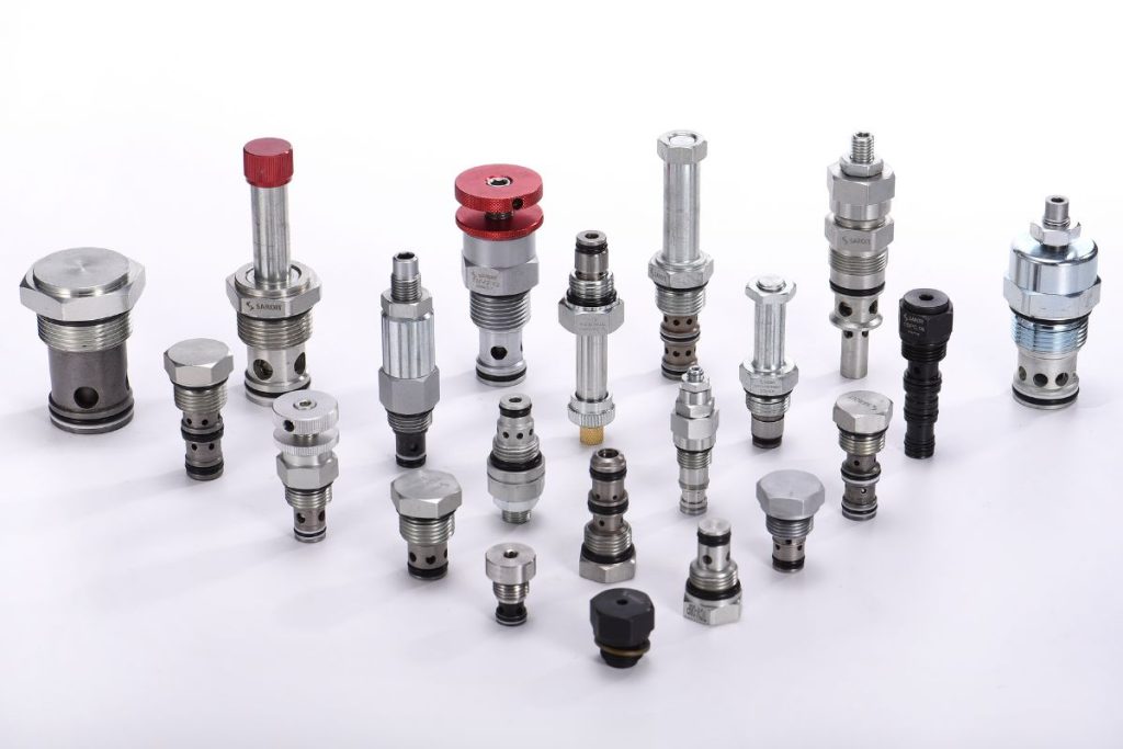
Drawings, selected-component documents and agreed acceptance criteria define the project scope. Product photographs are retained for context; they are not a test record, certificate or approved equipment configuration.
What cavity sizes do your cartridge valve manifolds support?
Provide the cavity drawing for each selected cartridge and the valve model documentation. A size or thread label is not sufficient to establish fit, passage alignment or function. Confirm the actual cavity and installation requirements against the manifold drawing.
How do I choose between two‑way and three‑way manifold logic?
Choose logic from the required equipment states and the actual valve schematic. Identify the pump, actuator, return and bypass paths for each command. A two-way or three-way label alone does not establish load holding or cylinder control.
Can I integrate a double‑acting cylinder circuit in one block?
A double-acting circuit needs defined pressure and return paths for both cylinder directions. The manifold can be reviewed around that schematic and selected valve list. Confirm holding, stopping, protection and power-loss behavior separately rather than assuming the block provides them.
What port standards and pressure ratings are typical?
Specify the thread standard, sealing method and port locations on the drawing. Permitted pressure must come from the selected block and valve documentation under the relevant operating conditions. Do not derive a universal pressure from the material name or port family.
Do you provide 2D/3D drawings for manifold and power pack integration?
Send the available schematic and dimensional drawing, identifying fixed interfaces and file-format requirements. Agree the drawing deliverables and revisions for the enquiry. A design review is not evidence that every requested format or configuration has already been released.
Which applications fit cartridge valve manifolds vs. CETOP stacks?
Compare the required functions, installation space, access and expansion needs. Cartridge blocks and modular valve stacks provide different integration paths; neither is automatically best for every mobile or industrial machine. Select the arrangement against the actual circuit and service requirements.
How should I control single‑acting cylinder lowering smoothly?
Define the load, return direction and required speed behavior on the schematic. Flow control and load holding are different functions, and the correct arrangement depends on the load and circuit. Have the equipment designer confirm the complete lowering and stopping behavior.
Can you customize manifold port sizes, materials, and stacking options?
Provide the required ports, cartridges, material constraints, mounting and assembly envelope. Confirm which dimensions and interfaces are fixed. Final customization scope, operating limits and drawings are agreed for the selected project, not inferred from a family description.
What information should I send for a quotation and design proposal?
Send the schematic, selected valve list, cavity details, operating pressure and flow, port standards and mounting envelope. Include command states and acceptance requirements. The enquiry establishes the drawing and supply scope before a project-specific quotation.
Send Your Cartridge Manifold Requirements
Related Component



Ready to Review the Equipment Requirements?
Send a drawing and a defined operating requirement.
Use the form on this page for the equipment inputs, fixed interfaces and required records. Final values follow the selected project documentation.