Counterbalance Valves for OEM Load-Control Circuit Review
Define the Load-Control Requirement
A counterbalance valve controls flow from a load-supporting actuator port to help restrain an overrunning load in a specified circuit. HydrathPower reviews the load, actuator, pilot supply and manifold interface before selecting a valve configuration.
Identify the required hold, commanded movement and power-loss states. The complete equipment design establishes safe behavior; the valve name alone does not guarantee zero drift, hose-failure protection or a fixed lowering speed.
Counterbalance Valve Functions
- Define the load-driving direction throughout the machine cycle.
- State the required holding and controlled-motion functions.
- Review available pilot pressure and load-side return flow.
- Confirm the response to loss of supply or control power.


Counterbalance Valve Symbols
Use the symbol and port description for the proposed valve model. Identify load, outlet, pilot and any vent connections on the released schematic.
Similar symbols or port counts do not establish equivalent operation. Confirm permitted free-flow direction, pilot arrangement and adjustment limits before integrating the component.
Where to Use Counterbalance Valves?
Lifting, tipping, positioning and hydraulic-motor circuits can involve loads that drive movement. Use those equipment names to start the review, not to approve a valve.
- Show how load direction changes with position.
- Identify the actuator port that supports the load.
- Include hold, start, stop and power-loss conditions.
- State the equipment safety and validation requirements.
Mounting, circuit architecture and the required failure response must be checked together. No generic application list verifies a hose-failure protection function.

Discuss the Load-Control Project
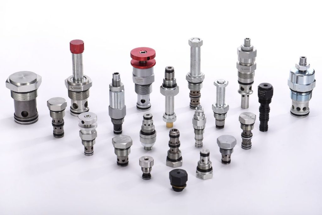
Provide the schematic and the load-control question you need to resolve. Confirm meeting dates and available model documents directly with HydrathPower before making arrangements. Exhibition photographs do not verify your component specification.
Review the Operating Sequence
Read the operating sequence against the proposed valve symbol. A check path may admit flow toward the actuator, while the controlled path governs outgoing load-side flow with the specified pilot arrangement.
- Supply: confirm the permitted flow direction and pressure drop.
- Hold: assess leakage, pressure and all relevant system paths.
- Commanded movement: review pilot availability and return-flow demand.
- Stop: define the required state and verify the complete circuit.
The force balance and response are model-dependent. Do not assume that raising is always cylinder extension or that a generic ratio produces stable movement in every installation.
Counterbalance Vs. Pilot‑Operated Check Valves
A counterbalance valve and a pilot-operated check valve have different release and motion-control behavior. Compare the required static holding and overrunning-load functions before selecting either path.
Include permissible leakage, pilot conditions, backpressure and the complete schematic. Neither component label alone establishes the machine’s drift or safety performance. Use the actual model documentation for any proposed substitution.
Counterbalance Valve Selection Inputs
| Review item | Information to provide | Decision |
|---|---|---|
| Load and geometry | Load direction, force or torque, positions and transients | Relevant load-supporting port |
| Actuator | Cylinder bore, rod and stroke, or motor data | Pressure and return-flow demand |
| Pilot supply | Available pilot pressure and control sequence | Opening and dynamic behavior |
| Backpressure | Return restriction and other operating circuits | Model and venting review |
| Duty | Travel times, repeated cycles and environment | Thermal and stability review |
| Interface | Cavity or mounting drawing, ports, seals and envelope | Manifold integration |
| Acceptance | Permissible motion/leakage and required failure response | Validation and documentation scope |
Record pressure in bar or psi and flow in L/min or US gpm. Identify measured conditions and drawing revisions. A body, cavity or pilot-ratio label does not replace the complete operating-point review.
Setting Counterbalance Valves
Adjustment and commissioning boundaries
Use the equipment and valve manufacturer’s approved procedure, limits and qualified personnel. Secure loads and manage stored energy through the approved method before work.
This page does not prescribe a universal load-pressure multiplier or an adjustment-under-load procedure. Agree on settings, required measurements and acceptance conditions for the identified valve and circuit. Investigate chatter, unexpected movement or leakage rather than repeatedly adjusting an unidentified component.
Why Choose Hydrath for Counterbalance Valves?
Send the load-control schematic, actuator information and interface drawing for HydrathPower’s component review. State which dimensions and operating conditions are known and which remain open.
Confirm the exact valve reference, permitted substitutions, installation instructions and required records with the quotation. Final performance and safety validation apply to the released equipment configuration. For the mechanism explanation, read the counterbalance valve operating-principle guide.