Features

Cartridge Solenoid Valves for OEM Directional Circuits

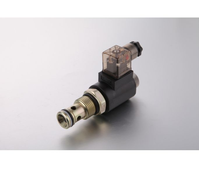
A cartridge solenoid valve uses an electrical coil to switch hydraulic flow paths within a specified manifold cavity. HydrathPower reviews the required energized and de-energized states, cavity drawing and electrical supply before selecting a valve and coil combination.

  • Function: provide the symbol and required default state.
  • Interface: identify the cavity, ports and sealing details.
  • Electrical: confirm voltage, connector and duty conditions.

Cartridge Solenoid Valves​ Types

Normally Closed Hydraulic Cartridge Solenoid Valve

Normally Closed Hydraulic Cartridge Solenoid Valve

A normally closed function blocks its specified path when the coil is de-energized. Confirm which ports are blocked, permitted reverse flow, leakage limits and energized behavior from the model documentation. Normally closed does not by itself establish a fail-safe machine state or a certified load-holding function.
Normally Open Cartridge Solenoid Valve

Normally Open Cartridge Solenoid Valve

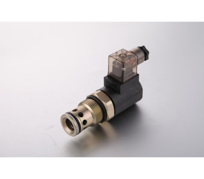
A normally open function leaves its specified path open when de-energized and changes that path when energized. Compare the symbol against the required resting, operating and power-loss states. Include flow direction, pressure at each port and permissible leakage in the model review.
Spool Type Solenoid Valve

Spool Type Solenoid Valve

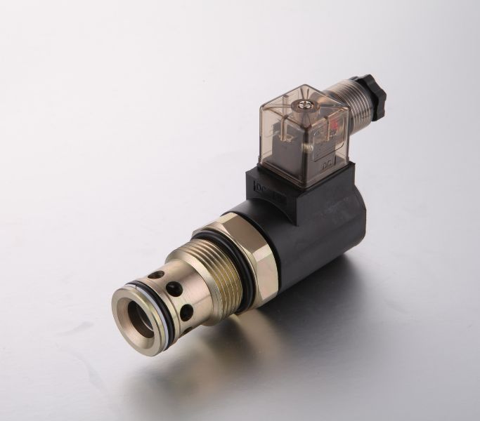
A spool cartridge switches paths according to its spool arrangement and position. Review all port connections and the center condition when applicable. Specify leakage requirements and the effect of supply or return pressure. A spool-type label is not evidence of proportional control or complete-circuit compatibility.
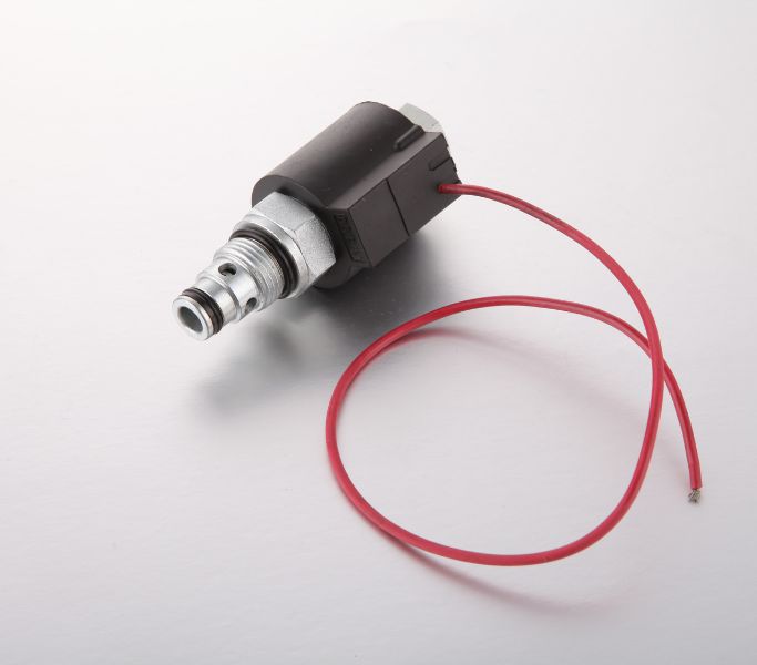
Poppet Type Solenoid Valve

Poppet Type Solenoid Valve

A poppet cartridge uses a seating element for its specified on/off function. Confirm the actual permitted flow direction, energized state, leakage limit and pressure conditions. Evaluate any holding or isolation requirement from the complete circuit and model data, rather than assuming every poppet valve provides the same behavior.
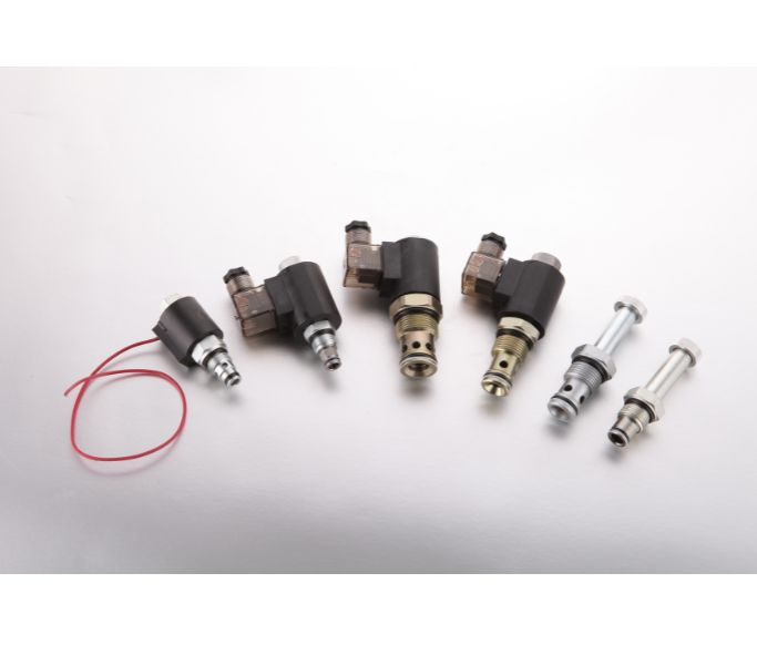
12V Hydraulic Solenoid Valve

12V Hydraulic Solenoid Valve

A 12V DC coil option must be matched to the valve operator and equipment electrical system. Provide voltage at the coil during starting and operation, connector details, control method and run/rest sequence. Confirm permitted duty and environmental requirements for the selected coil revision.
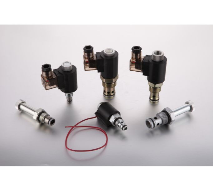
24V Hydraulic Solenoid Valve

24V Hydraulic Solenoid Valve

A 24V DC option identifies nominal electrical supply, not a hydraulic rating. Match the coil, valve operator, connector and controller output. Compare available voltage, current and duty using the proposed component data. Do not substitute coils solely because they fit over the same-looking tube.
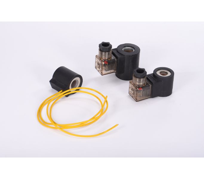
DC Coil Hydraulic Valve

DC Coil Hydraulic Valve

For a DC solenoid request, identify nominal supply, allowable voltage variation, switching sequence and operating duration. Include connector polarity or suppression requirements when applicable. Hydraulic pressure, leakage, flow and coil duty are separate checks and need documentation for the quoted combination.
Discuss the Valve and Manifold Review

Ask HydrathPower which technical drawings, model sheets and meeting options are available for your current project. Confirm exhibition dates and participation directly before arranging travel. This page does not establish an annual attendance record.

Cartridge Solenoid Valves Description & Models

Specify the flow state before selecting a cavity

Send the hydraulic symbol with port designations and the required position when the coil is energized and de-energized. A cavity designation describes an interface; it does not define the valve function or prove interchangeability with another supplier’s component.

Cartridge solenoid valve request sheet
Review itemInformation to provideDecision
Valve functionSymbol, positions, ports and default stateRequired flow paths
Hydraulic conditionsWorking pressure at each port, required flow and fluidModel limits and pressure-drop review
CavityCavity drawing, dimensions, sealing details and revisionManifold integration
ElectricalCoil voltage, connector, controller and switching dutyCoil/operator compatibility
LeakagePermitted leakage and the conditions in which it appliesIsolation or holding requirement
InstallationMounting space, coil removal clearance and exposureAssembly and service access

The catalogue tables below reproduce model-specific values from the existing site page captured on October 1, 2026. Confirm the applicable model sheet and revision before ordering. A 350 bar body-material entry is not a 350 bar rating for every complete valve assembly.

Review the complete hydraulic power-pack circuit when the valve is part of an assembly. For a new block, provide the hydraulic manifold interface drawing together with the valve request.

Existing catalogue model parameters

Model TSV‑08‑2NCP
NameSolenoid‑operated poppet valve, 2‑way, 2‑position, normally closed
Part NumberTSV‑08‑2NCP
Cavity08‑2
Operating Pressure207 bar
Internal Leakage2 drops/min max @ 207 bar
Working Temperature−40 → +100°C
Coil Duty RatingContinuous 85%–115% of nominal voltage
FluidsMineral‑based fluids, viscosity 7.4 → 420 cSt
Body Material & Max Pressure6061‑T6 aluminum rated 207 bar; Steel & ductile iron rated 350 bar
Coil ConnectionDouble lead; Single lead; Hirschmann 3‑pin
Voltage Options12VDC; 24VDC; 110VAC; 220VAC
Body PortingBlank; 4T = SAE4; 6T = SAE6; 2G = G1/4; 3G = G3/8
FlowSee PRESSURE DROP VS. FLOW graph
Model TSV2‑08‑2NOP
NameSolenoid‑operated poppet valve, 2‑way, 2‑position, normally open
Part NumberTSV2‑08‑2NOP
Cavity08‑2
Operating Pressure207 bar
Internal Leakage2 drops/min max @ 207 bar
Working Temperature−40 → +100°C
Coil Duty RatingContinuous 85%–115% of nominal voltage
FluidsMineral‑based fluids, viscosity 7.4 → 420 cSt
Body Material & Max Pressure6061‑T6 aluminum rated 207 bar; Steel & ductile iron rated 350 bar
Coil ConnectionDouble lead; Single lead; Hirschmann 3‑pin
Voltage Options12VDC; 24VDC; 110VAC; 220VAC
Body PortingBlank; 4T = SAE4; 6T = SAE6; 2G = G1/4; 3G = G3/8
FlowSee PRESSURE DROP VS. FLOW graph
Model TSV2‑10‑2NCP
NameSolenoid‑operated poppet valve, 2‑way, 2‑position, normally closed
Part NumberTSV2‑10‑2NCP
Cavity10‑2
Operating Pressure207 bar
Internal Leakage2 drops/min max @ 207 bar
Working Temperature−40 → +100°C
Coil Duty RatingContinuous 85%–115% of nominal voltage
FluidsMineral‑based fluids, viscosity 7.4 → 420 cSt
Body Material & Max Pressure6061‑T6 aluminum rated 207 bar; Steel & ductile iron rated 350 bar
Coil ConnectionDouble lead; Single lead; Hirschmann 3‑pin
Voltage Options12VDC; 24VDC; 110VAC; 220VAC
Body PortingBlank; 6T = SAE6; 8T = SAE8; 3G = G3/8; 4G = G1/2
FlowSee PRESSURE DROP VS. FLOW graph
Model TSV6‑12‑2NCRP
NameSolenoid‑operated poppet valve, 2‑way, 2‑position, normally closed
Part NumberTSV6‑12‑2NCRP
Cavity12‑2
Operating Pressure207 bar
Internal Leakage2 drops/min max @ 207 bar
Working Temperature−40 → +100°C
Coil Duty RatingContinuous 85%–115% of nominal voltage
FluidsMineral‑based fluids, viscosity 7.4 → 420 cSt
Body Material & Max Pressure6061‑T6 aluminum rated 207 bar; Steel & ductile iron rated 350 bar
Coil ConnectionDouble lead; Single lead; Hirschmann 3‑pin
Voltage Options12VDC; 24VDC; 110VAC; 220VAC
Body PortingBlank; 10T = SAE10; 12T = SAE12; 6G = G3/4; 8G = G1
FlowSee PRESSURE DROP VS. FLOW graph
RELATED

Related Component

Review Your Solenoid Valve Circuit

Let Our Engineering Experts Support You – Anytime.
Scroll to Top

Contact Us