
Hydraulic Flow Valves for Cartridge and Inline Circuits
A hydraulic flow valve meters oil flow to influence actuator speed in a defined circuit. HydrathPower presents needle, reverse-check and pressure-compensated flow-control configurations for cartridge and inline review. Select the function, port or cavity interface and pressure-drop behavior together; the valve name alone does not establish constant speed or safe load control.
Needle control changes a metering restriction. A reverse-check arrangement adds a defined freer-flow return direction; a pressure-compensated arrangement adjusts for changing pressure difference within its specified operating conditions.
Compare the actual model schematic, flow curve, port or cavity drawing and installation limits. An identical-looking cavity or adjustment knob does not prove equivalent function.
Match the flow-control function to the circuit
Hydraulic flow valves are selected by what the circuit must do with flow, not by cartridge size alone. Begin with the required actuator movement, controlled direction, reverse-flow behavior and change in load. Then review the valve interface and the pressure-drop data for the selected configuration.
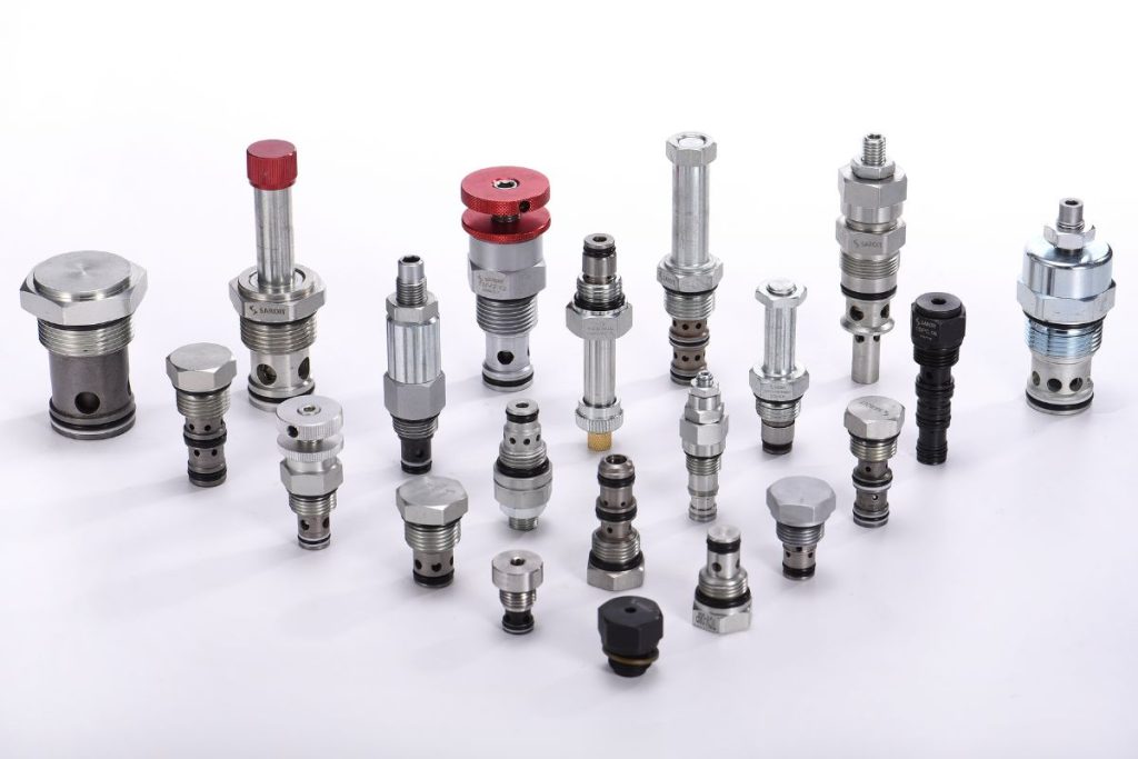
The existing range on this page identifies TNV2 adjustable needle valves, TFC one-way flow-control valves and TIFC in-line pressure-compensated valves. These are different selection paths. A similar connection size or shared product-family name does not mean they perform the same circuit function.
| Path | Circuit question | Selection check |
|---|---|---|
| TNV2 adjustable needle | Does the circuit require manual adjustment of a restriction? | Check adjustment range, flow direction and the pressure-drop/flow curve. |
| TFC one-way flow control | Should flow be metered in one direction with a reverse-check path? | Confirm the symbol, controlled direction and reverse-flow requirements. |
| TIFC in-line pressure compensated | Is a regulated-flow path needed as the operating load changes? | Check the selected model’s regulating conditions and available pressure differential. |
Selecting a cartridge flow control valve
A cartridge flow control valve must match both the circuit function and the manifold interface. Provide the cavity drawing or existing model documentation, the required controlled flow and the pressure conditions. A cavity designation alone does not establish functional interchangeability.
For integration into a manifold, confirm the port connections and passage routing shown on the schematic. State whether the controlled flow is associated with extension, retraction or another circuit branch. Keep those movement requirements separate from a general valve-family description.
Adjustable restriction or pressure-compensated flow?
A manually adjusted restriction provides a defined opening, but its resulting flow depends on the operating conditions. If load changes matter to actuator speed, compare that requirement with the regulating behavior of a pressure-compensated option. Check the model data rather than assuming that every flow valve keeps speed constant.
For a preset flow option, identify the target flow and the conditions at which it must be achieved. For an adjustable option, describe the adjustment range and whether the setting must be protected from unintended change. Neither option removes the need for a circuit review.
Check forward and reverse flow separately
State which direction must be metered and what should happen in the opposite direction. A free reverse-flow path can be useful in a circuit, but it is not the same function as a controlled return. The valve symbol and connections should agree with the required movement states.
Flow control should not be treated as proof of load holding or pressure protection. If the equipment has those requirements, specify them separately and review the complete arrangement. Confirm return behavior and power-loss behavior at equipment level before acceptance.
Interfaces and operating conditions for the enquiry
| Input | What to state |
|---|---|
| Hydraulic function | Metered direction, reverse-flow path, movement states and any separate load-control requirements. |
| Operating points | Required flow, pressure before and after the valve, and the range of load conditions. |
| Installation | Cartridge cavity or in-line connection drawing, port thread standard and available envelope. |
| Fluid and temperature | Fluid type, relevant temperature conditions and cleanliness requirements for the selected system. |
| Acceptance | Required adjustment, regulating performance, leakage criteria and the test conditions to be agreed. |
Discuss Your Flow-Control Circuit
Provide the circuit schematic, controlled direction, required flow range and available pressure conditions. Include the cartridge cavity or inline connection drawing and the installation space.
Current model documentation and supply scope are confirmed for the enquiry. Flow control is not, by itself, load-holding or equipment safety approval.
Components to Review with Flow Control


Ready to Define Your Flow-Control Requirements?
Start with the schematic and operating inputs.
Use the enquiry form to describe the metered direction, reverse-flow behavior, pressure conditions and cavity or port interface. Final values follow the selected model documentation.
Flow-valve questions
Can a flow control cartridge valve replace a needle valve directly?
Not on the basis of appearance or cavity size alone. Compare the hydraulic symbol, flow directions, regulating behavior and interface drawing. Confirm the specific circuit and model before treating an alternative as a replacement.
How does flow control relate to hydraulic cartridge valves?
Flow control is one function within the broader range of hydraulic cartridge valves. Other circuit functions can include directional and pressure control. Select the required function first, then check the cartridge’s interface and operating requirements.
Which pressure or temperature rating applies?
Use the selected valve and housing documentation, including the relevant material, seals, fluid and operating conditions. A family-level value is not a universal rating for every assembly. Confirm the agreed limits in the project package.
What should I send to HydrathPower?
Send the circuit schematic, movement requirements, controlled flow, pressure conditions and cavity or connection drawing. Identify whether manual adjustment, preset flow or a pressure-compensated path is needed. The existing enquiry action can be used to start the review; final model details and supply terms are confirmed for the project.