Features

Mini Hydraulic Power Packs for Restricted Installation Envelopes

A mini hydraulic power pack integrates the motor, pump, reservoir and valve circuit within a restricted installation envelope. HydrathPower reviews available space, actuator movement and electrical duty before confirming a compact configuration.

  • Space: include hose, connector and service clearances.
  • Motion: define powered directions and return behavior.
  • Duty: provide run/rest time and electrical supply.

MINI HYDRAULIC POWER PACKS: CONFIGURATIONS

12 Volt mini Hydraulic Power Pack​

12 Volt Hydraulic Power Pack

A 12V option starts with the equipment's available battery supply and charging arrangement. Provide voltage during starting and operation, cable run and duty sequence. Review the actuator and circuit within the mounting envelope. Nominal voltage does not determine pressure, usable oil volume or equipment suitability.

24 Volt Hydraulic Power Pack

A 24V option must match the electrical system and control interfaces. Confirm motor duty and hydraulic requirements rather than inferring heavy-duty performance from the voltage. Include connectors, cable entry and service access on the compact assembly drawing.
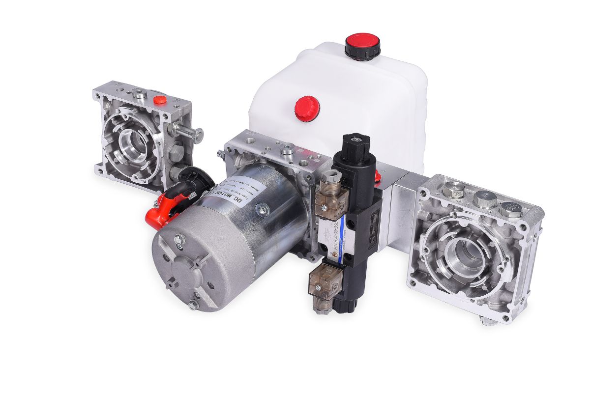
Dump Trailer Mini Hydraulic Pack

Dump Trailer Hydraulic Pack

For a dump-body installation, provide cylinder dimensions, load distribution, linkage geometry and target lift time. Define the external return force or powered return circuit. Show the allowed mounting envelope and reservoir orientation. Suitability and lowering behavior require the equipment-specific schematic.
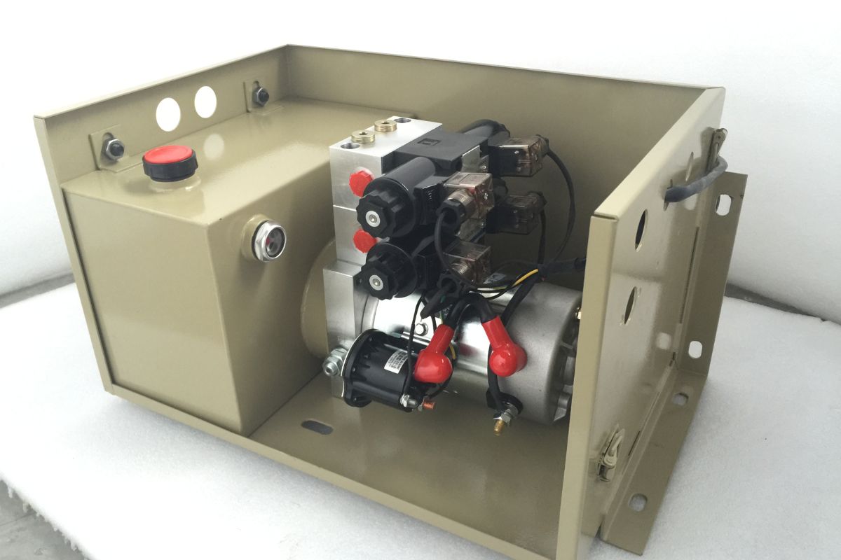
Liftgate Mini Hydraulic Pack

Liftgate Hydraulic Pack

A liftgate request needs the platform sequence, actuator arrangement, load, travel time and operating frequency. Include holding, emergency and power-loss states with the available electrical supply. Compact size alone does not validate the liftgate safety functions or expected operating duration.


Check the Complete Installed Envelope

Start with the space that remains after mounting brackets, hoses, electrical connectors and moving equipment are included. Show the installed orientation and service access on a dimensioned drawing.

Then match the circuit and operating point to that envelope. A tank-volume label does not establish usable oil volume at an incline, and a small outline does not prove adequate thermal duty. Review those requirements together before comparing compact assemblies.

Provide the existing schematic and interfaces for a replacement. Confirm component scope, drawing revision, inspection records and commercial terms for the quoted build. Product photographs do not verify an operating limit or acceptance result.

Mini power-pack envelope and operating input sheet
Review itemInformation to provideDecision
SpaceLength, width, height and obstruction drawingAssembly fit
Service accessFilling, inspection and component-removal clearanceMaintainability
ActuatorBore, rod, stroke, load and travel timeOperating point in each direction
Oil-level balanceActuator cycle, orientation and drain-backUsable reservoir volume
Electrical supplyVoltage under load, charging and cable runMotor and control interface
DutyRun/rest time, starts, ambient and temperaturesThermal and motor review
ConnectionsThread, sealing method, locations and hose bendsMechanical integration

Use dimensions in mm or inches, volume in L or US gal, pressure in bar or psi and flow in L/min or US gpm. Mark required, measured and proposed values separately. Final dimensions and ratings follow the released configuration drawing; this page does not apply one generic parameter range to every mini power pack.

Design: check fit and duty together

Compare the installed envelope with actuator motion, electrical supply and run/rest conditions. Include port access, hose bends and the reservoir operating level. Confirm the design revision before selecting components.

Manufacture: specify the interfaces

Identify manifold cavities, mounting, material, port threads and sealing requirements on the drawing. A cavity family name does not establish interchangeability. Agree on deburring, cleanliness and inspection requirements for the quoted scope.

Assembly: coordinate the component list

Align the motor, pump, manifold, valve functions and reservoir with the released schematic and bill of materials. Show which fittings, controls and electrical parts are supplied and which belong to the equipment builder.

Testing: agree on the conditions

Specify the functions, electrical conditions, pressure, flow, leakage and duty observations required for acceptance. Record units, drawing revision and agreed limits. A test-bench photograph is not a verified result for the ordered assembly.

Packaging: preserve the installation interfaces

Confirm port protection, handling, transport and storage requirements. Agree on accompanying drawings and required records. Retain the configuration and revision reference for later repeat orders or service.

Application

Hydraulic Power Packs Applications

Review a Compact Installation Project

Send the dimensioned envelope, operating sequence and circuit questions to HydrathPower. Confirm current meeting arrangements and any exhibition participation directly before planning travel. This page does not verify a recurring exhibition schedule.

What is a mini hydraulic power pack (mini power pack)?

A mini power pack is a compact assembly of a motor, pump, reservoir and valve circuit. Its suitability depends on the required operating point, duty and installation envelope. Compact size does not establish a standard tank volume or a universal pressure rating.

How do I choose between a 12V and 24V hydraulic power unit?

Use the supply supported by the equipment, then review voltage under load, charging, cable run and motor duty. A 24V label does not itself establish a larger hydraulic output or continuous operation. Confirm the complete motor and control specification for the installation.

What is the difference between single acting and double acting mini power packs?

Single-acting operation powers one direction and relies on an external return force. Double-acting operation powers both directions. Define holding, return-flow control and power-loss behavior separately; powered retraction is not automatically a safe-lowering function.

Provide the actuator, load, travel time, electrical supply, duty and installed drawing. Include usable oil volume, port details and service access. Final motor, pump, reservoir and valve selections must meet those inputs as a coordinated assembly.

Use the required flow at working pressure and the selected component data. Do not transfer a maximum pressure from another series to a mini configuration. The agreed assembly drawing and model documentation establish its permitted operating conditions.

Submit the trailer geometry, cylinder information, load and electrical supply for review. The external return force or powered return circuit needs a defined lowering and holding sequence. The application name alone does not confirm suitability.

A liftgate review must include the platform load, actuator arrangement, sequence, duty and required safety functions. Check installation space and service access alongside the hydraulic circuit. Equipment-specific validation is needed before treating a compact configuration as suitable.

Send the Envelope and Duty Inputs
RELATED

Related Component

Looking for Reliable Hydraulic Solutions?

Let Our Engineering Experts Support You – Anytime.
Scroll to Top

Contact Us