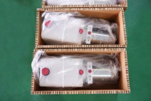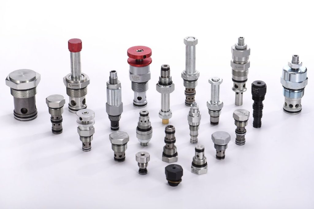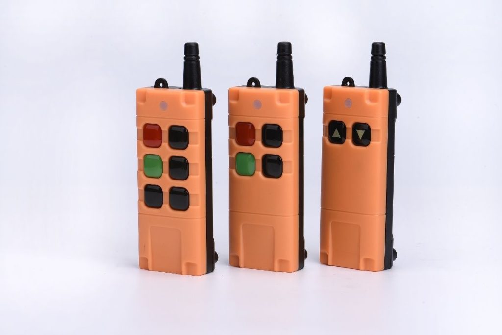
Features

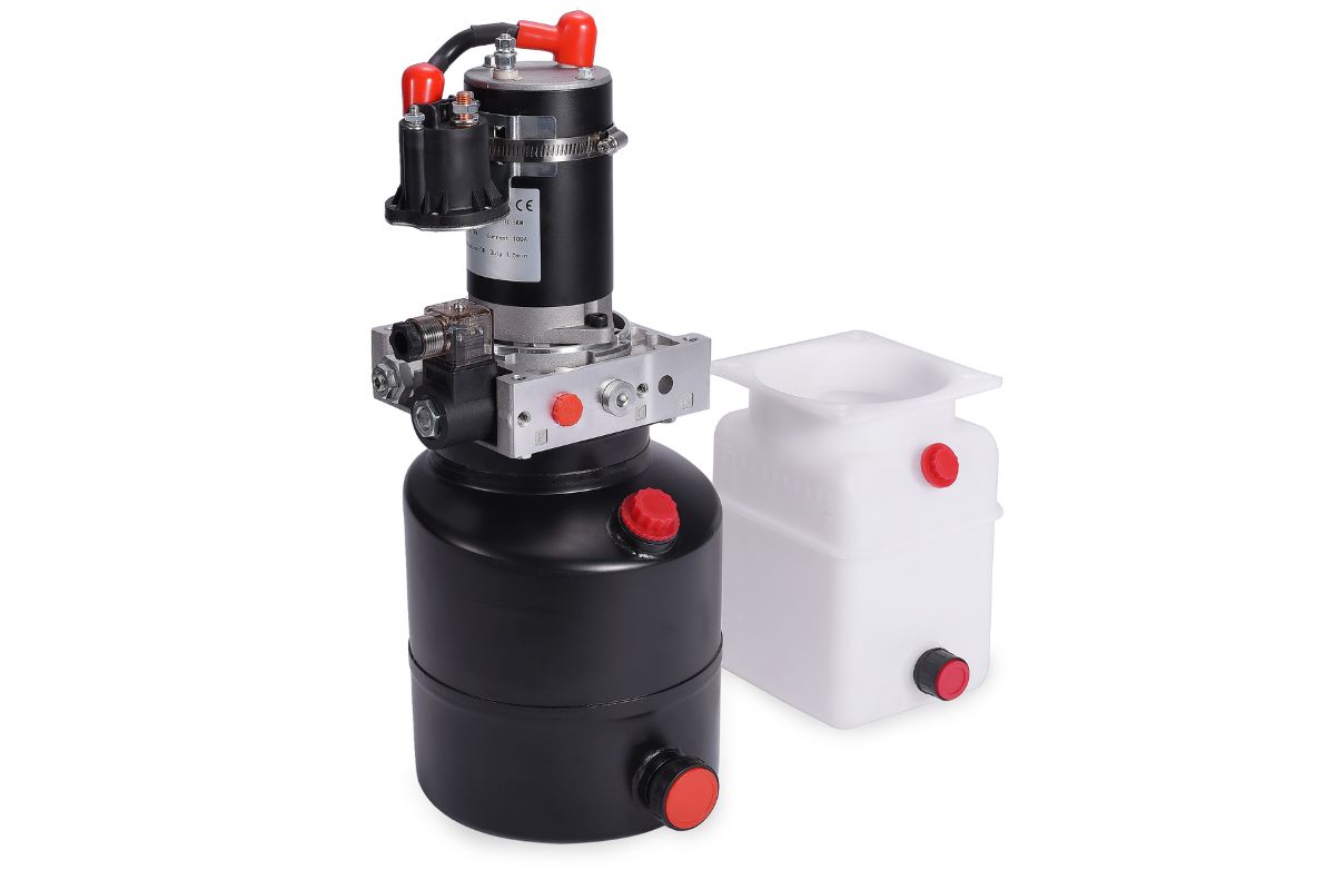
Electric Stackers Hydraulic Power Unit

An electric stackers hydraulic power unit supplies the lifting circuit of a battery-powered stacker. HydrathPower presents configuration paths for the lift cylinder, battery supply, lowering control and mounting envelope. Confirm the mast movement and return circuit for the actual machine; battery voltage or a generic flow range does not establish lifting capacity.

  • Lift duty: Provide load, cylinder dimensions, lift height and travel time.
  • Lowering: Describe controlled return, holding and power-loss requirements on the circuit.
  • Integration: Confirm battery supply, reservoir orientation, ports and chassis mounting.

ELECTRIC STACKERS HYDRAULIC POWER UNIT TYPES

12V Electric Pallet Stacker Power Unit

12V Electric Pallet Stacker Power Unit

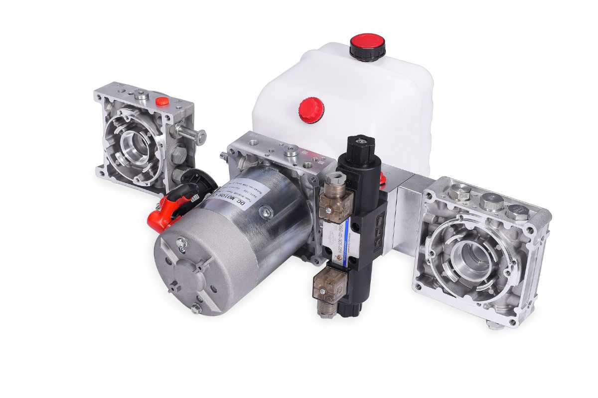
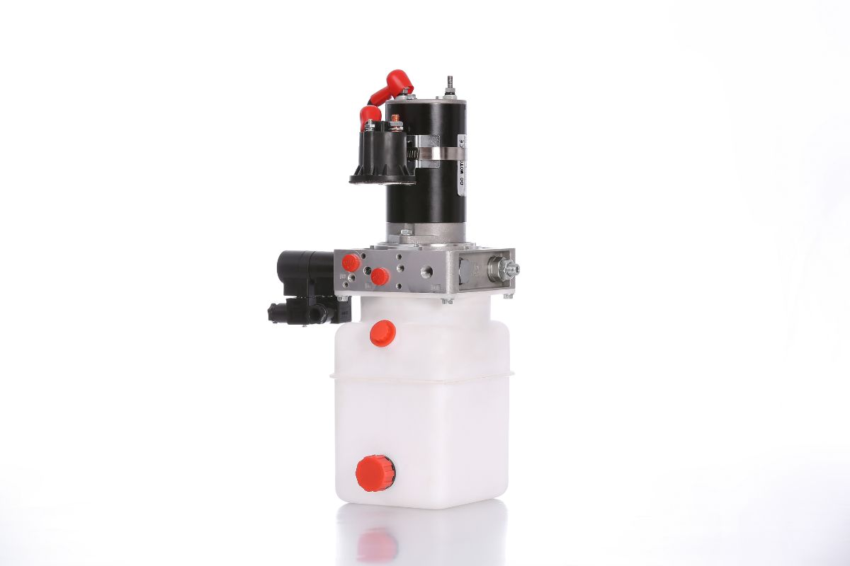
For a 12V electric pallet stacker power unit, provide battery and charging information together with cylinder dimensions and target lift time. Show the chassis envelope and reservoir orientation. Confirm the selected motor and hydraulic operating points; 12V does not establish the machine's lifting capacity.
24V Electric Pallet Stacker Power Unit

24V Electric Pallet Stacker Power Unit

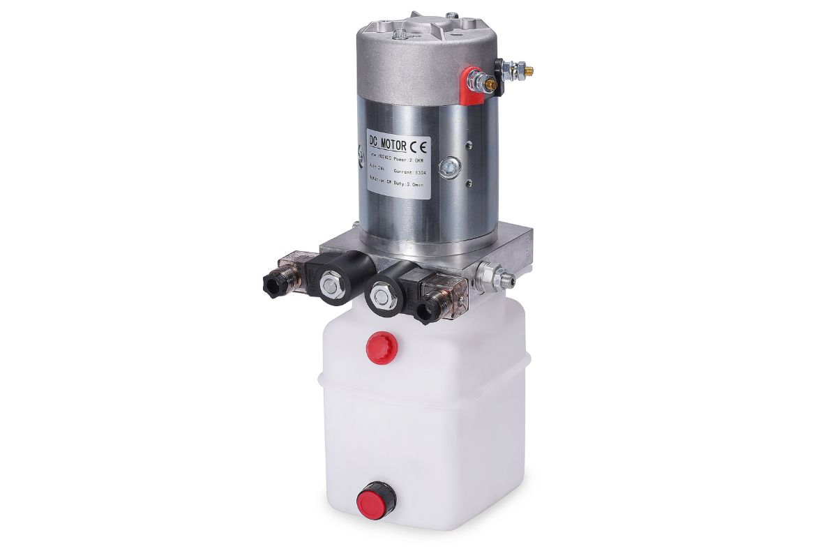
A 24V electric pallet stacker power unit must match the actual battery, controls and required cycle. Review motor duty, pressure and flow using the mast and cylinder inputs. A 24V label does not by itself guarantee a faster response, better efficiency or longer operating time than another configuration.
Single-acting Stacker Power Unit

Single-acting Stacker Power Unit

A single-acting stacker circuit uses powered lift and an external return force for lowering. Confirm that the mechanism can return under the specified load range and define holding and lowering-control requirements. The valve arrangement must match the complete mast and cylinder circuit rather than a generic preset-pressure description.
Double-acting Stacker Power Unit

Double-acting Stacker Power Unit

A double-acting stacker circuit provides powered movement in both directions when the mechanism requires it. State the required neutral, holding and power-loss behavior separately. Confirm cylinder and valve functions together; powered lowering alone does not establish load control, machine safety or a particular speed.

Define the Stacker Lifting and Lowering Package

Send the stacker mast and cylinder information with the battery and chassis drawing. Separate the machine load rating from the pressure rating of a power-unit component. Confirm the proposed circuit, motor duty, lowering behavior and required tests against the complete machine specification; the hydraulic power unit alone does not establish overall stacker safety or capacity.

On small screens, scroll the table horizontally to read every column.

Configuration review inputs
DecisionInputs to provideWhy it matters
Mast and loadRated machine load, lift height and mechanism geometryAssess cylinder requirements through the lift.
Cylinder motionBore, stroke and lift/lower timingDetermine hydraulic operating points.
Return controlLowering behavior and load-control requirementsReview the actual valve and cylinder circuit.
BatterySupply under load, charging and repeated startsCheck motor and electrical protection.
Chassis fitMounting drawing, reservoir and port locationsConfirm access and the installation envelope.

Application

Review the Stacker Duty and Related Lift Tasks

Discuss Your Mast and Battery Inputs

Send the stacker mast and cylinder drawing, battery information and required lift/lower sequence for review. Identify the chassis space and service-access constraints. Confirm project and meeting details directly with HydrathPower rather than treating an exhibition image as a current event listing.

What voltage, power, flow and pressure are typical for an electric stacker hydraulic power unit?

Confirm voltage from the machine electrical system and determine pressure and flow from the mast, cylinder and movement requirements. Motor power and duty must then be reviewed for those operating points. The selected drawing and documentation establish final values; there is no single preset that defines every electric stacker hydraulic power unit.

When should I choose single‑acting vs double‑acting circuits for stackers?

Choose from the required return mechanism. Single-acting circuits rely on an external force for return; double-acting circuits can use powered flow in both directions. Controlled lowering and load holding still require a suitable valve circuit in either case. Assess the actual mast and cylinder arrangement rather than assuming double acting is automatically safer.

how do I decide for battery runtime and lift speed?

Match voltage to the battery, charger, controls and selected motor. Compare the actual motor-pump performance and duty at the required lift conditions. A 24V system is not inherently faster or longer-running simply because its voltage is higher; the complete electrical and hydraulic configuration determines those results.

Calculate the oil-volume change through the full cylinder travel and review the usable reservoir volume in its installed orientation. Include the return path, service level, temperature conditions and access. Confirm the selected tank arrangement rather than applying a generic capacity range to every mast and circuit.

Pressure must be determined from the load path, cylinder areas, mechanism geometry and allowable component limits. Confirm the working conditions and pressure-protection arrangement for the complete machine. Do not increase a relief setting to obtain an unapproved load capacity; adjustment and verification belong to the qualified equipment procedure.

Use the cylinder displacement and required travel time to establish the flow demand, then compare the pump displacement, speed and efficiency at the operating point. Include the actual motor supply and duty. Verify the complete combination rather than copying a generic displacement-to-flow range from a different stacker.

List the work ports, thread and sealing details, pump and reservoir connections, and required valve functions on the schematic. Define lift, hold, lower and power-loss states. Confirm how directional, pressure and load-control functions are implemented for that machine; port size and manifold appearance do not establish circuit compatibility.

State the permitted lowering behavior across the intended load range and review the cylinder and valve circuit for those conditions. Include fluid temperature, return routing and the installation environment. Noise and motion quality need agreed acceptance conditions; changing one valve or mounting part does not guarantee a particular result.

Follow the selected power unit and machine maintenance instructions. Record fluid condition, filtration requirements, electrical condition, leakage observations and changes in operation. Inspection must follow the equipment’s isolation and load-support procedures; generic intervals or undocumented relief adjustments are not a substitute for the approved plan.

State the required behavior for power loss and any emergency lowering function in the machine specification. Confirm whether the proposed assembly includes the necessary controls and how they are used in the approved procedure. Do not assume manual release or a check valve alone provides an acceptable emergency function for every stacker.

Get an Instant Quote Now

RELATED

Related Component

Looking for Reliable Hydraulic Solutions?

Let Our Engineering Experts Support You – Anytime.

Scroll to Top

Contact Us