
Hydraulic Cylinders for Load, Stroke and Mounting Review
A hydraulic cylinder converts pressurised oil into linear movement. HydrathPower presents single-acting, double-acting, telescopic, welded, tie-rod and custom cylinder paths for OEM review. Select the movement, load path, stroke and mounting together; a family name does not establish the rating or suitability of a delivered cylinder.
HYDRAULIC CYLINDERS TYPES
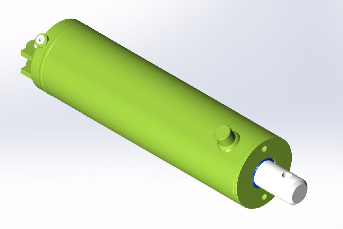
Single‑acting Hydraulic Cylinder
Single-acting movement requires a defined external return and release path. Provide the load, stroke, mounting and holding requirements; confirm the selected cylinder and circuit together.
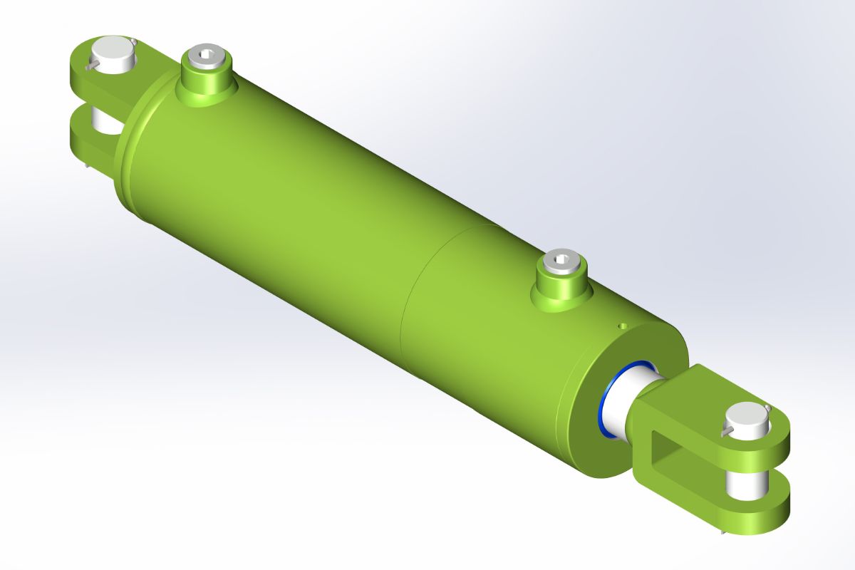
Double‑acting Hydraulic Cylinder
Double-acting movement is powered in both directions. Compare extend and retract force, stroke volume and speed, and provide the mounting and port drawing for the equipment.
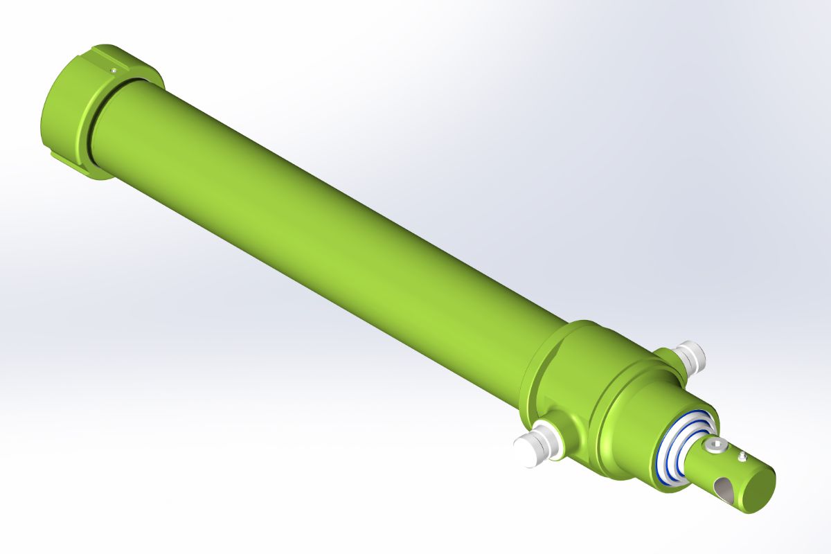
Telescopic Hydraulic Cylinder
A telescopic path uses multiple stages to obtain travel within a constrained retracted length. Check the load and geometry through extension rather than selecting by total stroke alone.
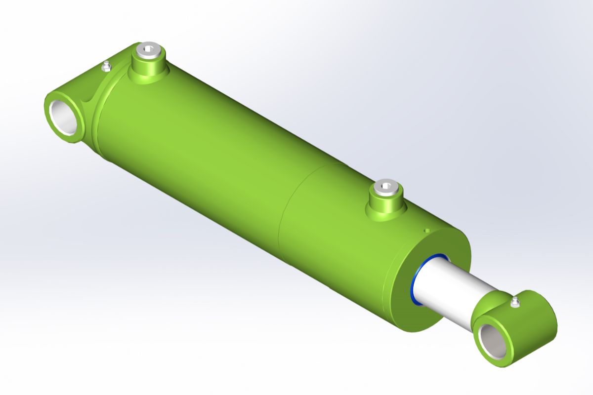
Welded Hydraulic Cylinder
A welded-cylinder path should be reviewed by the installation drawing, load path, ports and service requirements. The construction name does not establish a fixed pressure or dimensional match.
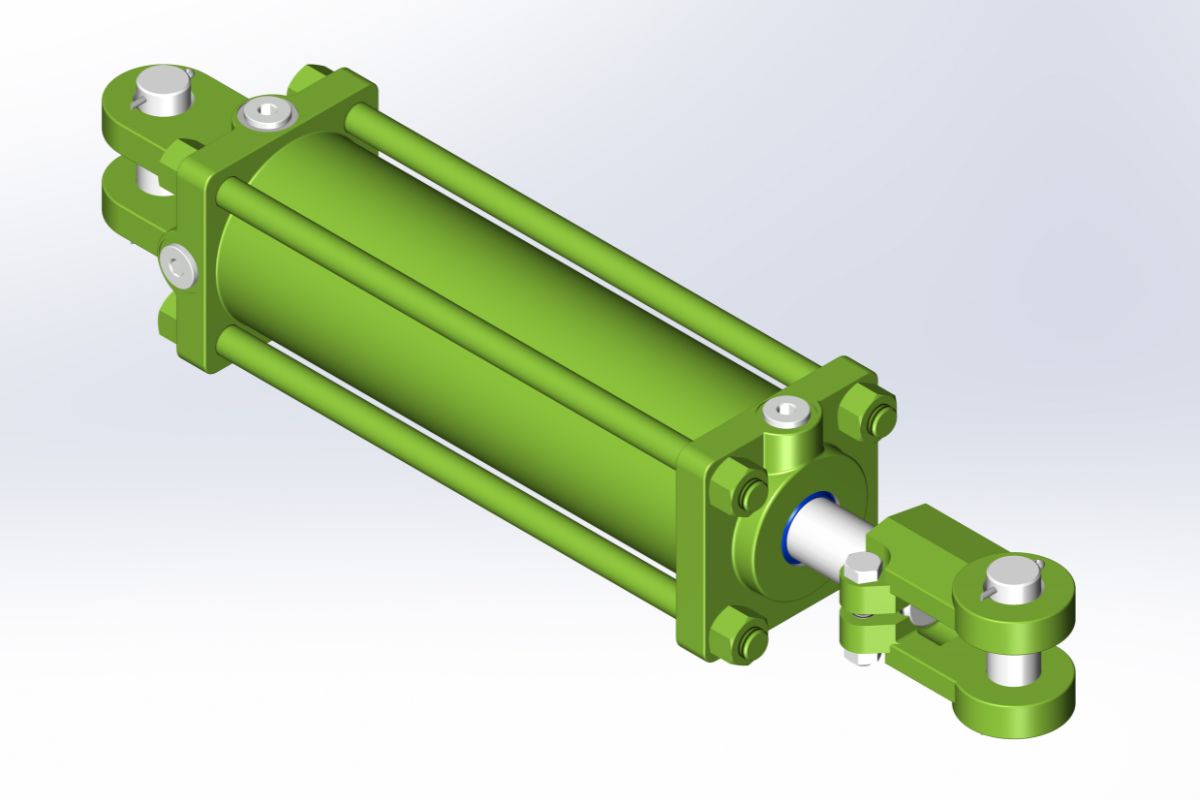
Tie‑rod Hydraulic Cylinder
A tie-rod-cylinder path needs a confirmed envelope, mounting, port arrangement and service plan. Similar external dimensions are not proof of interchangeability or compliance.
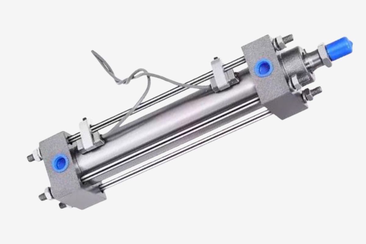
Custom Hydraulic Cylinder
A custom-cylinder enquiry starts with movement, load, travel, mounting and operating conditions. Agree final dimensions, materials and acceptance evidence on the project drawing.
Hydraulic Cylinder Drawing and Selection Review
HydrathPower reviews the available schematic, equipment drawing and operating inputs for the product path shown here. Identify the interfaces that must stay unchanged and the information needed for engineering confirmation.
Drawings, selected-component documents and agreed acceptance criteria define the project scope. Product photographs are retained for context; they are not a test record, certificate or approved equipment configuration.
Hydraulic Cylinder Drawing and Selection Review
Begin with the equipment movement rather than a cylinder diameter taken from a photograph. Specify load, travel, motion direction and the available installation length.
Separate hydraulic sizing from mechanical support. Pressure and effective piston area affect force; mounting geometry, rod extension and guidance affect how that force is transmitted.
| Selection input | What to provide | What it resolves |
|---|---|---|
| Load and movement | Load direction, operating sequence and required powered movements. | Cylinder action and the load cases that need review. |
| Stroke and envelope | Required travel, closed length and available extension space. | Installation fit throughout the motion, not only at rest. |
| Bore and rod | Proposed dimensions or the force and speed inputs used to select them. | Force, oil volume and rod-side differences. |
| Mounting | Pin, clevis, flange, foot or trunnion drawing and movement geometry. | Alignment, load transfer and support conditions. |
| Ports and hoses | Thread standard, locations, routing and service clearance. | Actual connection and interference checks. |
| Fluid and environment | Fluid type, temperature, contamination and exposure conditions. | Seal, material and protection requirements. |
| Acceptance | Drawing revision, inspection criteria and required records. | The definition of the delivered configuration. |
Choose the cylinder action
A single-acting cylinder uses hydraulic pressure for one powered direction and an external return force where the design permits it. A double-acting cylinder uses pressure on either side for powered movement in both directions.
Specify how the load behaves during holding, stopping and power loss. The cylinder alone is not proof of a complete load-holding or safety arrangement.
Compare construction and installation length
Welded and tie-rod constructions provide different installation and service paths. Compare the mounting and dimensional drawing rather than assuming that a construction label establishes interchangeability.
A telescopic cylinder uses multiple stages to provide travel within a shorter retracted envelope. Stage geometry and the load through the extension sequence need separate review.
Check both directions of movement
For a conventional single-rod, double-acting cylinder, the rod reduces effective area on one side. Extension and retraction can therefore have different force and speed at equivalent pressure and flow.
State the required cycle time for each direction. Include stroke volume, return flow and the complete circuit in the review; bore alone does not define the cycle.
Define alignment and end-of-stroke behavior
Identify how the machine guides the load and how the mounting follows movement. The cylinder should not be treated as a substitute for missing mechanical guidance.
Where cushioning or stopping behavior matters, define speed, moving mass and the permitted end-of-stroke behavior. Confirm the selected arrangement with the equipment designer.
Send an enquiry that can be checked
Use the form on this page for the load, stroke, cylinder action, mounting drawing, operating conditions and required acceptance records. Include an existing part only as a comparison reference.
Final dimensions, materials, seals, operating limits and supply scope are confirmed on the selected project documentation. No general family range is an approval for a particular machine.



Hydraulic Cylinder Application Inputs

Vehicles & trailers
For vehicles & trailers, provide vehicle power, load, travel and return behavior. Review the hydraulic cylinders configuration against those inputs. An application category or photograph is not compatibility or safety approval.

Material handling
For material handling, provide lifting geometry, cylinder inputs, sequence and holding requirements. Review the hydraulic cylinders configuration against those inputs. An application category or photograph is not compatibility or safety approval.

Industrial & automation
For industrial & automation, provide machine sequence, operating points and simultaneous functions. Review the hydraulic cylinders configuration against those inputs. An application category or photograph is not compatibility or safety approval.

Marine & off‑grid
For marine & off‑grid, provide available drive, environment, mounting and service access. Review the hydraulic cylinders configuration against those inputs. An application category or photograph is not compatibility or safety approval.

Agriculture & livestock
For agriculture & livestock, provide adjustment or working movement, repeated cycles and equipment interfaces. Review the hydraulic cylinders configuration against those inputs. An application category or photograph is not compatibility or safety approval.

Medical & disabled access
For medical & disabled access, provide the intended equipment function and its safety and acceptance requirements. Review the hydraulic cylinders configuration against those inputs. An application category or photograph is not compatibility or safety approval.
Send Your Cylinders Project Inputs
Use the existing enquiry form on this page for the available drawing, operating conditions and installation requirements. Include the required documents and acceptance criteria.
The enquiry confirms current model information and the project supply scope. Do not treat a past event or product photograph as evidence of a delivered configuration.
What core parameters define a hydraulic cylinder?
Provide the required movement, load, stroke, installation envelope, mounting, ports, fluid and operating conditions. Bore and rod dimensions should be checked against those inputs. Final limits and interfaces belong to the selected drawing, not to a universal range for every hydraulic cylinder.
How do I select port threads and sizes for a hydraulic cylinder?
State the actual thread standard, sealing method and connection drawing. Check port position, hose routing and available flow conditions as well as nominal size. Similar thread diameters do not establish compatible connections.
What speed limits and cushioning options apply to hydraulic cylinders?
Speed and cushioning requirements depend on the moving load, circuit and stopping conditions. Define the acceptable end-of-stroke behavior and provide the motion inputs. Do not apply one speed limit or cushioning threshold to every cylinder family.
How to avoid side‑load and misalignment on hydraulic cylinders?
Review mounting geometry and the machine guidance across the full stroke. Show alignment, pin interfaces and any changing load direction on the drawing. The equipment designer must assess side loads and rod support; a general mounting name is not an acceptance check.
Which fluids and seal materials are compatible with hydraulic cylinders?
Provide the actual hydraulic fluid and temperature conditions, together with contamination or chemical exposure. Confirm seals and materials for the selected configuration. A material name alone does not establish compatibility with every fluid or environment.
What pressure ranges are typical by application for hydraulic cylinders?
Use the pressure limit in the selected cylinder documentation and check the operating and peak conditions defined for the circuit. An application category does not establish one allowable pressure. Confirm relief, load-control and acceptance requirements separately.
What maintenance practices reduce leakage and extend hydraulic cylinder life?
Follow the equipment and cylinder service instructions. Inspection should address external damage, leakage, alignment, rod condition and fluid condition as appropriate to the installation. Do not replace a defined maintenance plan with a general promise of service life.
What testing and documentation should accompany hydraulic cylinders?
Agree the drawing revision, material or seal information, inspection criteria and required test records before release. Where a standard or certificate is required, identify the actual scope and document needed. This page does not certify every cylinder or prescribe a universal proof-pressure multiplier.
Send Your Cylinders Requirements
Related Component


Ready to Review the Equipment Requirements?
Send a drawing and a defined operating requirement.
Use the form on this page for the equipment inputs, fixed interfaces and required records. Final values follow the selected project documentation.