Wheelchair Lift Hydraulic Power Pack
- A wheelchair lift hydraulic power pack supplies flow to move a lift platform through its specified cylinder and valve circuit.
- HydrathPower reviews cylinder motion, load, supply voltage and the installation envelope for each enquiry.
- Confirm flow, pressure, reservoir capacity and motor duty against the complete lift specification.
- Agree the acceptance tests and required records before configuration approval.
- Noise and Motion Requirements: Specify noise and movement requirements for the complete lift and its installation.
- DC Supply Review: Match the 12V/24V motor and controls to the vehicle supply and voltage under load.
- Motor Duty and Protection: Confirm the motor’s rated duty and specified protection; do not assume a thermal switch permits repeated operation beyond that rating.
- Load-Holding Requirements: Define allowable leakage, holding behavior and fault response for assessment at complete-lift level.
- Emergency Procedure Review: Confirm the lift manufacturer’s approved backup and lowering procedure for the exact model.
- Installation Envelope: Check mounting, hose routing and service access against the vehicle installation drawing.
| Parameter | Specification |
|---|---|
| Voltage | 12V DC / 24V DC / 48V DC |
| Motor Power | 0.8kW – 2.2kW |
| Max Pressure | 160 Bar – 250 Bar (2300 – 3600 PSI) |
| Flow Rate | 1.2 LPM – 4.5 LPM |
| Pump Displacement | 0.5cc – 2.1cc / rev |
| Duty Cycle | S3 – 10% to 15% (Intermittent) |
| Tank Capacity | 1.5L / 2.5L / 4.0L / 8.0L |
| Tank Material | UV-resistant Plastic or Steel |
| Mounting Orientation | Horizontal or Vertical |
| Fluid Type | ISO VG 32 or 46 Hydraulic Oil |
Your Reliable wheelchair lift Hydraulic Power Pack China Supplier
Your wheelchair lift application demands a solution that prioritizes passenger safety and long-term reliability. Hydrath understands the engineering challenges of compact spaces and battery-powered systems, offering customized manifold designs and high-torque motors that reduce installation time and maintenance costs.
Are you ready to optimize your lift design? Invite us to review your drawings or technical requirements today. We promise to provide competitive pricing, a realistic build plan, and engineering support that accelerates your time-to-market.
Request a quote now to start your Hydrath journey.
Application
Hydraulic Power Packs Applications


Agriculture & livestock
- Lifting
- Feeding
- Rural automation systems

Wheelchair Lift Hydraulic Power Pack Design
- Compact System Layout: Designed around a low-noise DC motor, precision gear pump, and compact oil reservoir for confined spaces.
- Custom Flow & Pressure: Flow rate, relief setting, and tank capacity are matched to target lift speed and load needs.
- Installation-Friendly Interfaces: Port locations, mounting pattern, and wiring exits are defined early to reduce rework.
- Comfort-Oriented Motion: Gentle, stable movement is prioritized for wheelchair lift applications requiring smooth control.


Hydraulic Manifold Block Manufacturing
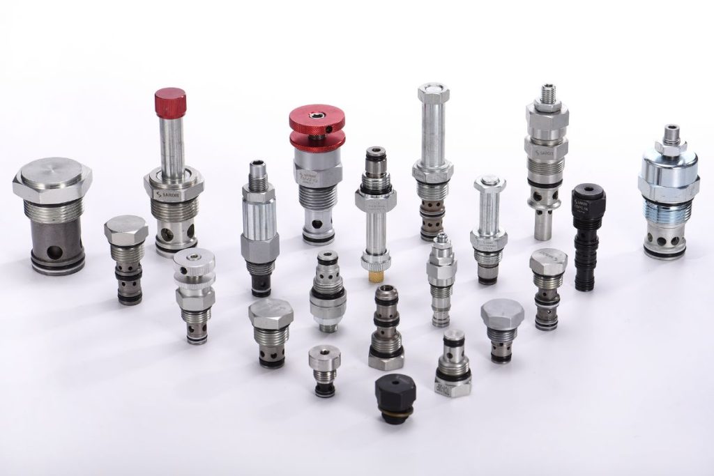
- Valve Cavity Precision: Manifold blocks are machined for cartridge valves, relief valves, check valves, and solenoid valves to support stable holding.
- Clean Internal Galleries: Deburring and cleaning reduce contamination risk for the gear pump and valve system.
- Material Options: Aluminum manifold blocks are available to balance weight, corrosion resistance, and pressure margin.
- Leak-Control Focus: Sealing faces and interfaces are processed to support low leakage and consistent performance.
Wheelchair Lift Hydraulic Power Pack Assembly
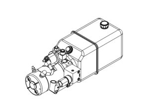
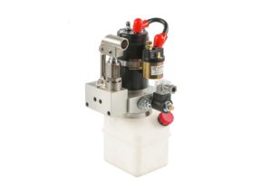
- Complete Power Pack Integration: DC motor, gear pump, manifold, solenoid valve, and oil tank are assembled as a ready-to-install hydraulic power unit.
- Wiring & Coil Compatibility: 12V/24V solenoid coil selection and harness routing are arranged for serviceable layouts.
- Seal & Fitting Consistency: Hose routing, fittings, and sealing points are standardized to reduce field leaks.
- Emergency Function Ready: Manual override and emergency lowering components can be integrated for safer operation.


Wheelchair Lift Hydraulic Power Pack Testing
- Pressure & Leakage Verification: Each hydraulic power pack is checked for sealing performance across manifold, valves, and connections.
- Flow Performance Check: Gear pump output is confirmed to deliver predictable lifting speed with the chosen oil reservoir.
- Smoothness & Noise Review: Low-noise operation and stable motion are validated for mobility lift comfort expectations.
- Emergency Function Test: Manual override and emergency lowering response are verified for practical reliability.
Meet Us on The Trade Show
Hydrath attends exhibitions worldwide every year:
Hannover Messe
PTC ASIA
Bauma CHINA
You are welcome to book a visit to our exhibitions.
What type of hydraulic fluid is typically used in wheelchair lift power units?
Use the fluid specified in the exact lift manufacturer’s current manual. Confirm its viscosity grade and compatibility with the selected hydraulic components.
Do not substitute ATF or another fluid solely because ambient temperature is low; obtain the equipment manufacturer’s approval.
Follow the model-specific inspection and replacement schedule, adjusted only through the manufacturer’s maintenance guidance.
Why is a DC system preferred?
Wheelchair lifts are usually installed on vehicles (vans, buses), and the 12V or 24V DC system can directly utilize the vehicle’s battery power without the need for an additional inverter.
Its compact structure and high energy efficiency make it ideal for mobile equipment.
What is the "S3 intermittent duty cycle"?
Check the selected wheelchair lift motor’s duty rating before planning repeated cycles.
S3 describes intermittent periodic duty; the permitted run/rest cycle depends on the motor’s stated rating and operating conditions.
Follow the motor and lift documentation; a duty label alone is not a guarantee against overheating or failure.
How do I check the hydraulic fluid level?
Check the reservoir when the platform is fully lowered to the ground (cylinder retracted).
The fluid level should be around the “full” mark indicated on the reservoir.
If the fluid becomes cloudy or dark, it needs to be replaced.
What should I check first if the lift won't unfold or retract?
1. Power Switch: Ensure the power switch at the bottom of the power unit is turned on.
2. Circuit Breaker: Check if the circuit breaker near the vehicle battery has tripped.
3. Door Limit Switch: Most systems require the vehicle door to be fully open to activate the safety limit switch.
4. Seatbelt: Some models require the seatbelt to be fastened before power is supplied.
Why is the platform lifting slowly or jerking?
1. Low Voltage: Insufficient battery power or corroded terminals can cause a voltage drop.
2. Low Oil Level: Low hydraulic fluid level causes the pump to draw in air.
3. Clogged Filter: Accumulation of debris on the suction filter restricts flow.
How do I manually operate the lift during a power failure?
Check the exact lift model’s operator manual for its approved manual backup or emergency-lowering procedure. Do not loosen hydraulic fittings or unidentified valve screws to lower a platform. If the procedure or component identification is unclear, stop using the lift and contact a qualified service provider.
What are "Safety Catches"?
These are mechanical safety devices that, in the event of accidental pressure loss in the hydraulic system, will catch the platform to prevent it from suddenly falling or unexpectedly unfolding.
What is the purpose of a zero-leakage solenoid valve?
It is crucial for ensuring the platform remains stable at its highest position for extended periods. Without this valve, the platform might slowly “sink” due to minor internal leakage.