Electric Motor for HPU

Electric Motors for Hydraulic Pump Integration

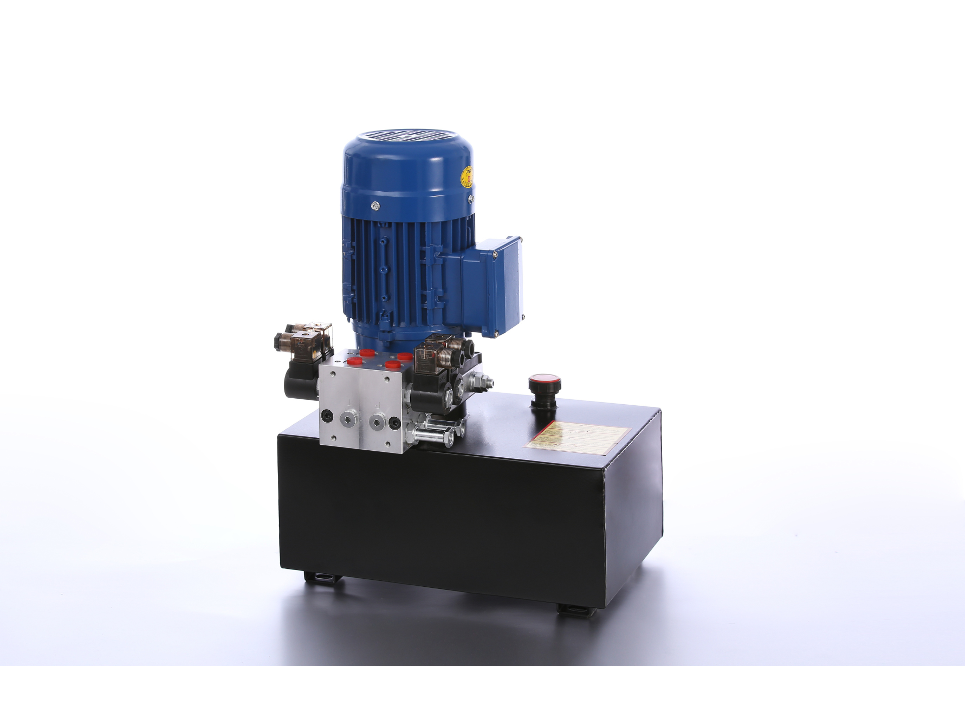
An electric motor for hydraulic pump duty drives the pump at the speed and torque needed by the hydraulic operating points. HydrathPower presents AC and DC motor paths for hydraulic power-pack integration. Select the electric motor for hydraulic power pack use from the available supply, pump interface and duty cycle, not from voltage or nominal power alone.

  • Operating points: Provide pressure, flow, pump displacement and required shaft speed.
  • Duty and starting: State run/rest times, starting conditions and repeated starts.
  • Interfaces: Confirm shaft, flange, coupling, mounting and protection requirements.

OUR PRODUCT

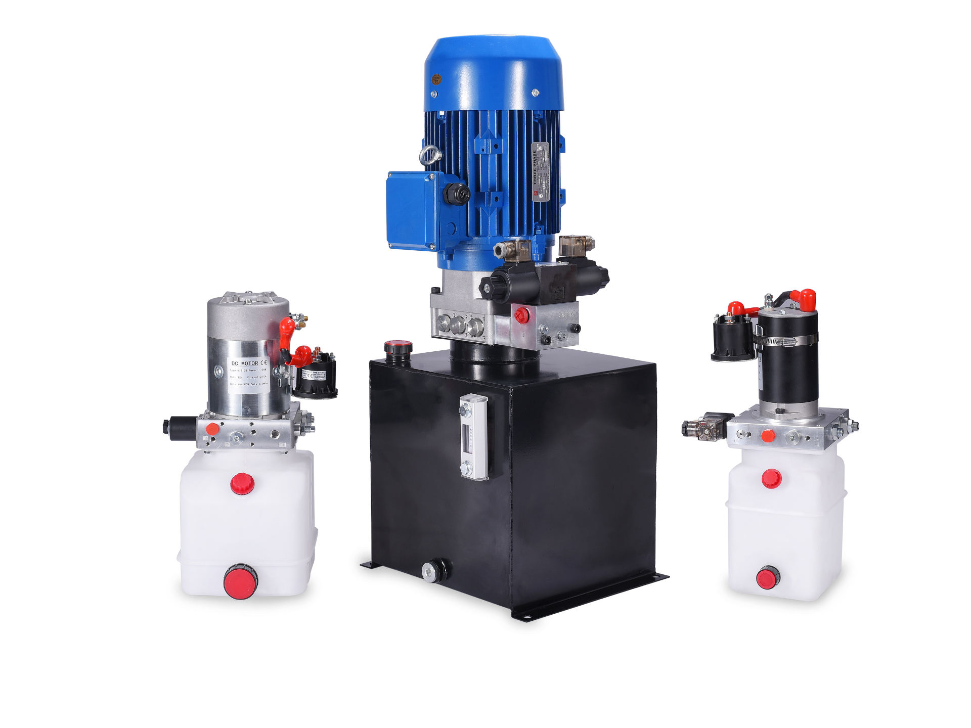
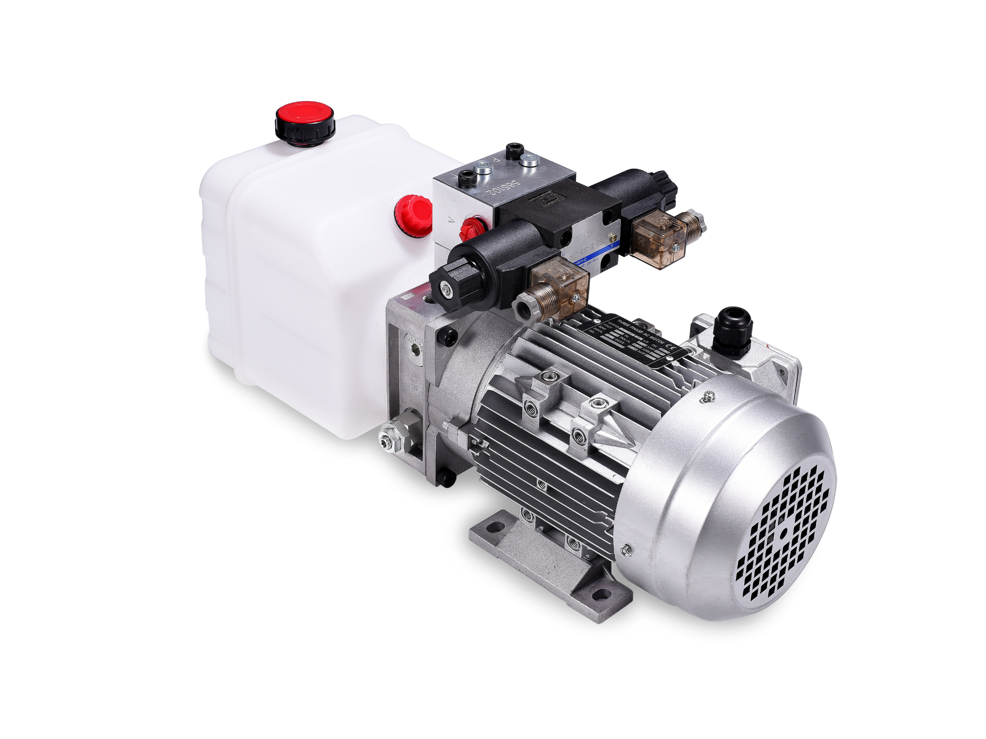
Electric Motor For Hydraulic Power Packs

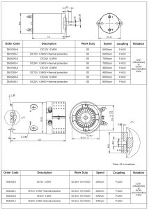
DC Motor

DC Motor

Select a DC motor from the available supply and the pump's required speed and torque. Include the starting condition, repeated starts and run/rest sequence. Confirm the motor rating, switching devices and pump interface together; a compact frame or DC label does not establish continuous-duty capability.

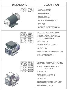
AC Motor

AC Motor

For an AC motor, confirm voltage, phase, frequency, starting method and duty before comparing nominal power. Check shaft speed against the pump and required flow. The selected nameplate and datasheet must support the proposed installation; mains supply alone does not prove continuous duty or an efficiency class.

12V DC Motor​

12V DC Motor

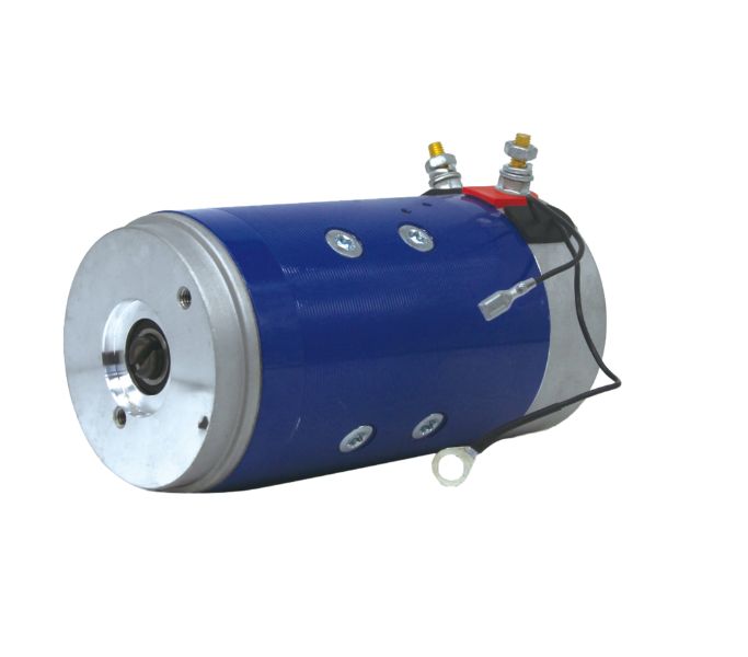
A 12V DC motor must be reviewed with the battery, charging arrangement, cable route and switching components. Provide the pump operating points and expected starts. Confirm the actual motor performance and thermal limits under the required conditions rather than selecting from voltage alone.
24V DC Motor

24V DC Motor

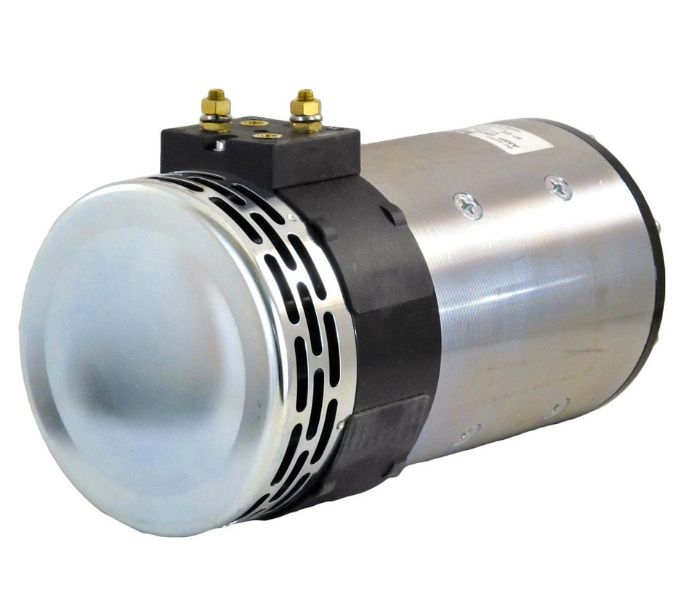
For a 24V DC motor, match the entire electrical path to the machine supply and required motor duty. Check pump torque, speed, shaft and mounting interfaces. Do not assume a particular relay size, overload capability or performance benefit without the selected motor and control documentation.
Brushless DC Motor

Brushless DC Motor

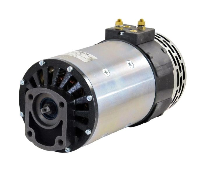
A brushless DC motor needs a compatible driver and defined command and feedback interfaces. Review the required speed range, starting torque, cooling and fault behavior with the pump. Efficiency, noise and service-life claims require model-specific conditions and evidence; brushless construction alone does not quantify those results.
3‑phase AC Motor

3‑phase AC Motor

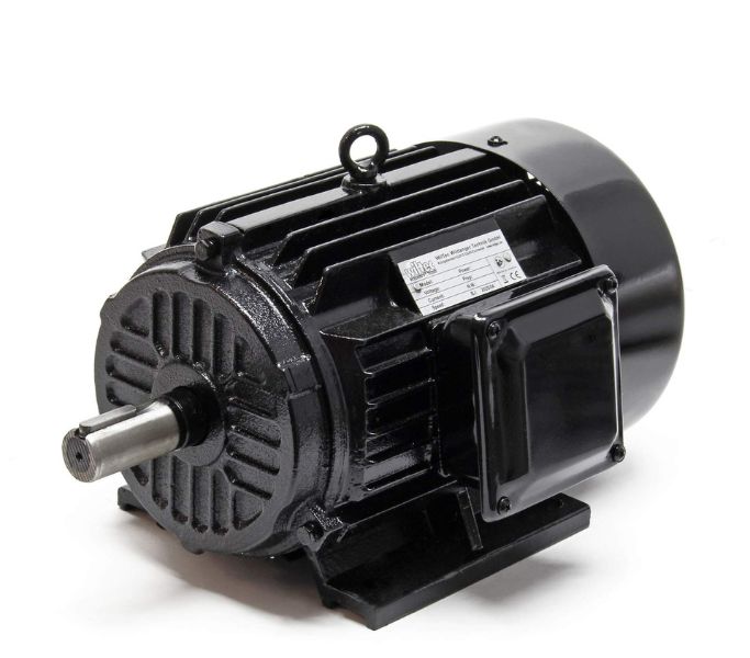
A three-phase AC motor enquiry should identify the site voltage and frequency, connection arrangement, starter and operating duty. Confirm the required shaft speed and starting load with the pump. Any efficiency or protection rating must come from the selected motor documentation and apply to the actual configuration.
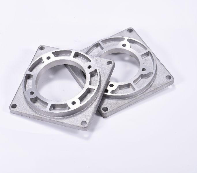
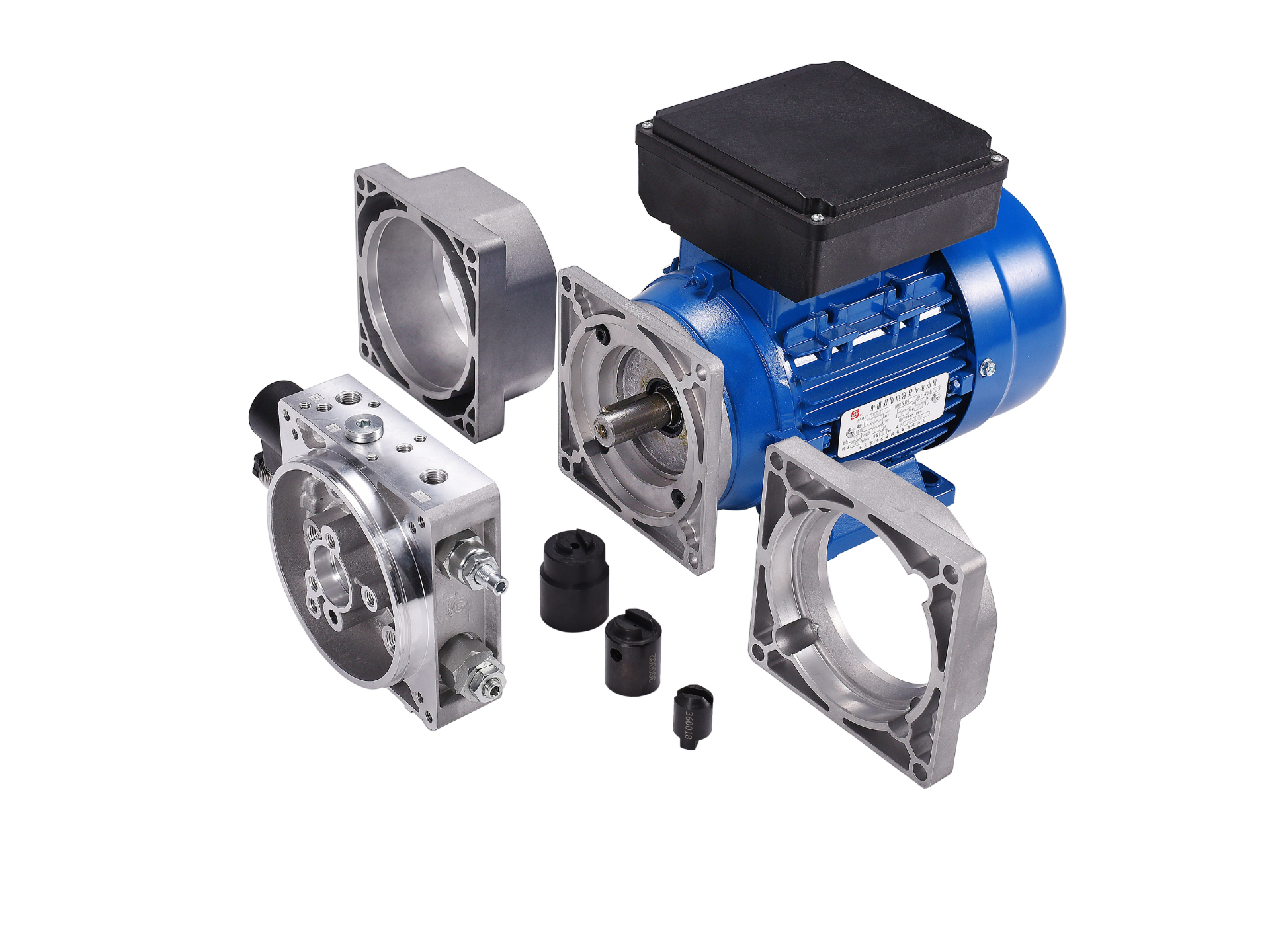
B5 B14 Motor Flange

B5 B14 Motor Flange

For a B5 or B14 motor flange, compare the complete dimensional drawing with the pump and coupling. Check shaft diameter and extension, pilot, bolt pattern, alignment and available space. A flange designation alone does not guarantee fit, acceptable vibration or interchangeability with an existing assembly.

Discuss the Motor and Pump Match

Send the pump drawing, required operating points and available electrical supply for a motor-selection discussion. Include the intended operating cycle and starting conditions. Confirm appointments and project requirements directly with HydrathPower; existing event photographs do not establish a current schedule.

Application

Motor Duty Across Hydraulic Applications

Gallery

Electric Motor Gallery

FAQ

How do I choose between DC and AC electric motor for a hydraulic pump?

Choose AC or DC from the available supply and the required motor duty. DC does not automatically mean intermittent duty, and AC does not automatically mean continuous duty. Confirm the selected motor nameplate, speed, starting method and thermal limits together with the pump and machine operating sequence.

On small screens, scroll the table horizontally to read every column.

Configuration review inputs
DecisionInputs to provideWhy it matters
DC pathBattery supply, cable run and duty cycleDo not infer continuous duty from a DC label.
AC pathVoltage, phase, frequency, starting method and dutyDo not infer continuous duty from mains supply alone.
Pump matchSpeed, torque, shaft, flange and couplingConfirm motor and pump drawings together.
EnvironmentCooling, temperature and required protection evidenceConfirm the selected motor nameplate and datasheet.
How do I size motor power and speed for my pump?

Begin with the pump’s required operating points and displacement, then confirm its permitted speed and the shaft torque needed. Include starting against the actual circuit conditions and the complete run/rest pattern. Review the motor curve, nameplate and thermal limits for that duty; a typical rpm figure is not a substitute for the selected motor data.

S1 denotes continuous duty under the specified rating conditions; S3 denotes intermittent periodic duty. Read the complete duty designation and relevant conditions for the selected motor. Compare the machine cycle and starting pattern with that documentation instead of assuming every industrial motor is S1 or every compact DC motor is S3.

Describe water, dust, cleaning, ambient temperature and mounting conditions before specifying protection. Confirm the enclosure rating and installation instructions for the selected motor, including cable entries and cooling. A generic IP label should not be treated as approval for every outdoor or washdown environment.

Compare the motor and pump drawings for shaft size, pilot, bolt pattern, flange dimensions and coupling engagement. Include the mounting envelope and alignment requirements. Verify the actual parts together; B5 or B14 wording alone does not establish that an existing motor can be replaced without interface changes.

Yes. The motor must start the pump under the conditions imposed by the hydraulic circuit and electrical supply. Record whether the start occurs unloaded or against pressure, along with repeated starts and the required acceleration. Have the motor and pump combination reviewed using the selected performance data and protective arrangement.

Consider BLDC when the project requires a compatible electronically controlled motor path and the driver can meet the pump duty. Define speed range, command interface, feedback and fault behavior. Compare measured or documented results for the proposed combination; noise, efficiency and maintenance benefits should not be assumed without that evidence.

Specify switching and protection from the selected motor, supply and installation requirements. A qualified electrical reviewer should confirm starting current, cable path, protective devices and thermal protection. Do not copy a relay current rating or accessory kit from a different motor family merely because the frame looks similar.

Get an Instant Quote Now

RELATED

Related Component

Looking for Reliable Hydraulic Solutions?

Let Our Engineering Experts Support You – Anytime.
Scroll to Top

Contact Us