
Mobile Hydraulic Power Units for Vehicle and Field Integration
A mobile hydraulic power unit supplies hydraulic flow where the equipment carries its own power source or works away from a fixed installation. HydrathPower presents DC and engine-driven mobile HPU paths for equipment review. Define the hydraulic movement, available power, mounting and operating cycle together; mobility does not establish one pressure, flow or duty rating.
MOBILE HYDRAULIC POWER UNIT TYPES
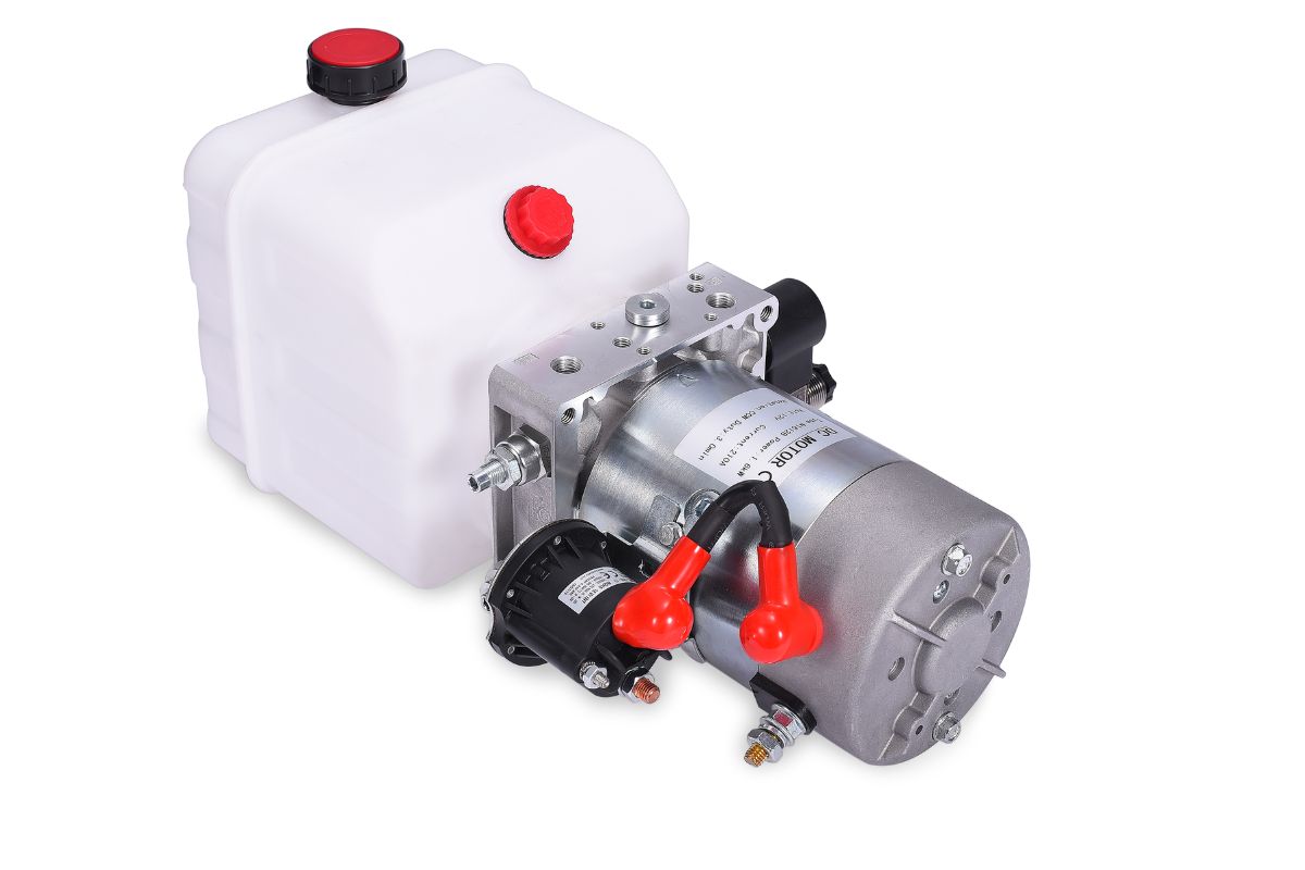
DC Hydraulic Power Unit
For a DC mobile HPU, provide the battery and charging arrangement, operating voltage, circuit and run/rest cycle. Confirm the drive and hydraulic operating point together.
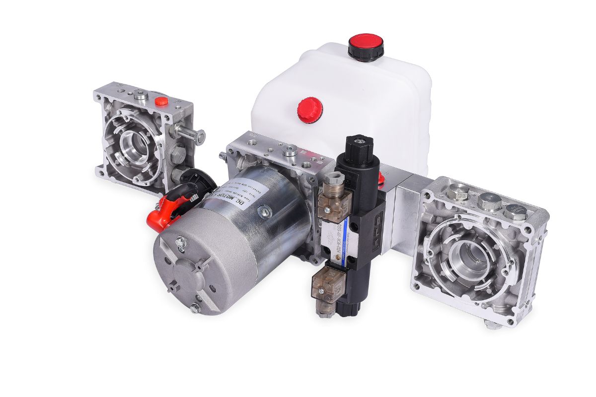
12v Hydraulic Power Unit
A 12V path begins with the available vehicle supply and its behavior during starting and operation. Include the cable route, charging, cylinder function and repeated-cycle requirement.
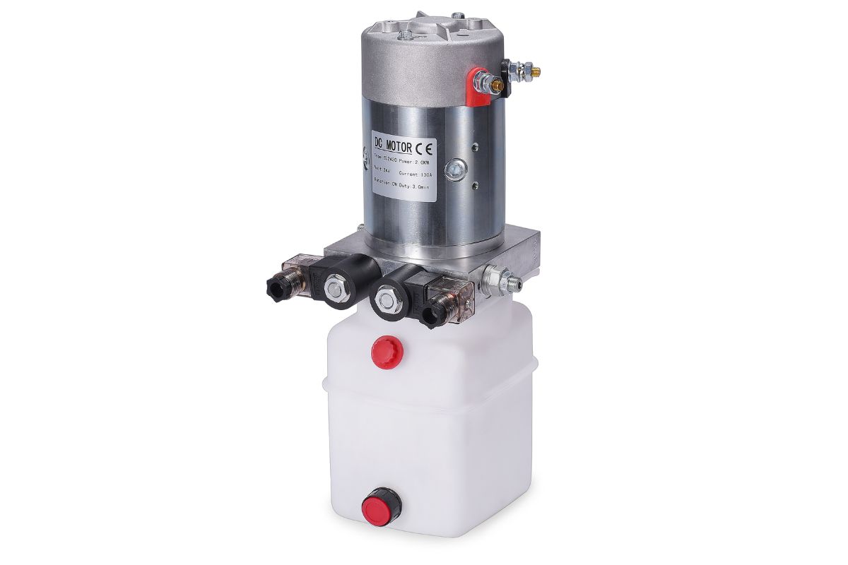
Scissor Lifts Mobile HPU
A mobile scissor-lift review needs the mechanism geometry, load, cylinder inputs and required stop or holding states. A family photograph is not a lift-system safety approval.

Truck Tail lift Hydraulic Power Unit
A tail-lift review requires the load, lift geometry, powered and return directions, electrical supply and mounting. Confirm the circuit with the equipment designer.
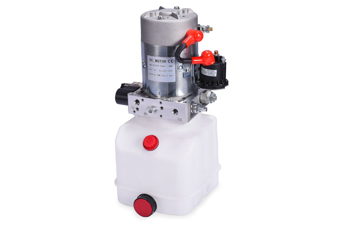
Dump Trailer 12v HPU
A dump-trailer review begins with the tipping geometry, cylinder, return behavior and available battery supply. Confirm usable oil volume and duty for the full tipping sequence.

Gasoline/diesel Mobile HPU
An engine-driven review needs the selected drive interface, speed conditions, hydraulic operating points and installation environment. Mobility does not establish one universal output rating.
Mobile HPU Power-Supply and Mounting Review
HydrathPower reviews the available schematic, equipment drawing and operating inputs for the product path shown here. Identify the interfaces that must stay unchanged and the information needed for engineering confirmation.
Drawings, selected-component documents and agreed acceptance criteria define the project scope. Product photographs are retained for context; they are not a test record, certificate or approved equipment configuration.
Mobile HPU Power-Supply and Mounting Review
Begin with the movement the mobile equipment must perform and the power source actually available at that installation. Include normal operation, return behavior and the required power-loss state.
A vehicle battery label is only one input. Starting conditions, wiring, charging and repeated cycles must be reviewed against the selected drive and hydraulic operating point.
| Selection input | What to provide | What it resolves |
|---|---|---|
| Equipment function | Load, movement, cylinder or tool and target cycle. | Required pressure, flow and circuit states. |
| Power source | Battery and charging arrangement or selected engine-drive inputs. | The drive and available-power path. |
| Operating cycle | Run/rest time, repeated starts and ambient conditions. | Duty and thermal requirements. |
| Installation | Orientation, mounting drawing, available space and vibration/exposure inputs. | Assembly envelope and equipment interfaces. |
| Return and holding | Required lowering, stopping and power-loss behavior. | Valve and load-control review. |
| Reservoir | Stroke oil requirement, return routing and service access. | Usable volume and layout. |
| Controls | Operator commands, wiring, connectors and interlocks required by the machine. | Electrical and machine-control integration. |
Choose the power path before the package
A battery-powered and an engine-driven unit can serve different installation needs. State the available power and required operating point before comparing package size.
For DC review, include supply behavior during starting and operation, cable route and charging. For engine-drive review, identify the selected drive interface and speed conditions.
Review mounting and orientation
Provide the equipment frame drawing, assembly envelope and orientation. Include the reservoir relationship, port access and hose routing.
Describe vibration, weather exposure and service conditions as project inputs. A mobile label does not establish an enclosure protection or corrosion rating.
Define controlled movement and power loss
Identify which directions are powered and how the actuator returns. Specify stop, hold, release and power-loss states on the schematic.
Flow control is not the same as load holding. A compact integrated manifold must still be reviewed as part of the equipment circuit.
Match repeated cycles to usable oil and heat
Provide the stroke oil requirement, full sequence and run/rest cycle. Distinguish nominal reservoir size from oil available throughout movement.
Include surrounding temperature and installation ventilation. Do not infer continuous operation from drive type or a cooling photograph.
Send a mobile HPU enquiry
Use the existing form for the equipment function, supply or drive, circuit, duty, mounting drawing and environment. Include the battery and charging inputs where the drive is DC.
Final drive, pressure, flow, reservoir, controls and operating limits belong to the project documentation. A general application card is not approval for the installation.



Mobile Hydraulic Power Units Application Review

Vehicles & trailers
For vehicles & trailers, provide vehicle power, load, travel and return behavior. Review the mobile hydraulic power units configuration against those inputs. An application category or photograph is not compatibility or safety approval.

Material handling
For material handling, provide lifting geometry, cylinder inputs, sequence and holding requirements. Review the mobile hydraulic power units configuration against those inputs. An application category or photograph is not compatibility or safety approval.

Industrial & automation
For industrial & automation, provide machine sequence, operating points and simultaneous functions. Review the mobile hydraulic power units configuration against those inputs. An application category or photograph is not compatibility or safety approval.

Marine & off‑grid
For marine & off‑grid, provide available drive, environment, mounting and service access. Review the mobile hydraulic power units configuration against those inputs. An application category or photograph is not compatibility or safety approval.

Agriculture & livestock
For agriculture & livestock, provide adjustment or working movement, repeated cycles and equipment interfaces. Review the mobile hydraulic power units configuration against those inputs. An application category or photograph is not compatibility or safety approval.

Medical & disabled access
For medical & disabled access, provide the intended equipment function and its safety and acceptance requirements. Review the mobile hydraulic power units configuration against those inputs. An application category or photograph is not compatibility or safety approval.
What is a mobile hydraulic power unit?
A mobile HPU provides hydraulic flow for a vehicle-mounted, portable or field installation using the available drive source. Selection needs the equipment movement, power source, mounting and operating cycle. Confirm the complete configuration rather than choosing from mobility alone.
12V vs 24V for mobile HPU — which to choose?
Match the equipment supply and the selected motor requirements. Include voltage under load, starting, charging, wiring and the required hydraulic operating point. A 12V or 24V label alone does not establish load capacity, efficiency or duty.
How to size pressure/flow for tail lifts?
Provide the lifting geometry, load, cylinder dimensions and required cycle times. Review raise, lower, hold and power-loss states on the schematic. Pressure and flow follow the equipment inputs; do not apply one family range to every tail lift.
What reservoir size for dump trailers?
Use the cylinder stroke volume, return behavior, installation orientation and operating cycle to review usable oil capacity. Include thermal and service constraints. A trailer type or a fixed catalogue tank size does not establish the final reservoir.
ATEX requirements for mobile HPUs?
If the intended installation has hazardous-location requirements, identify the location classification and required conformity documents with the equipment owner and qualified reviewer. Do not treat this general mobile HPU page as evidence of an ATEX-approved assembly. Confirm the actual product scope and documents before selection.
Send Your Mobile Hpu Requirements
Related Component



Ready to Review the Equipment Requirements?
Send a drawing and a defined operating requirement.
Use the form on this page for the equipment inputs, fixed interfaces and required records. Final values follow the selected project documentation.