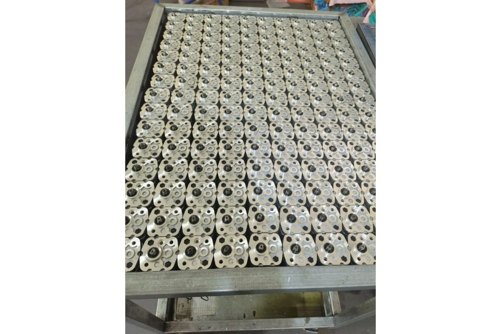
Hydraulic gear pump selection inputs
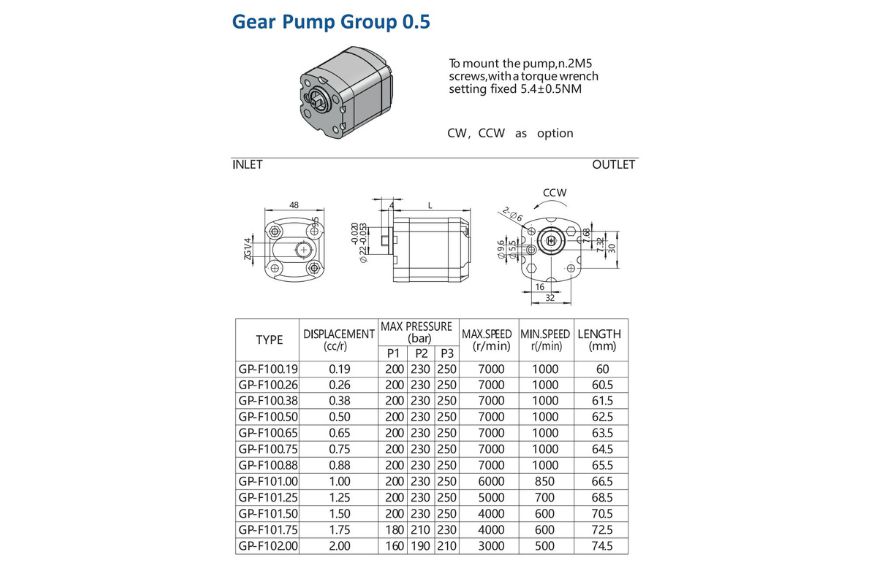
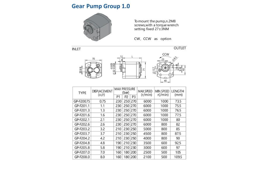
A precision gear pump must match the required flow, the drive speed and the equipment interfaces. HydrathPower’s existing range is organised around Group 0.5 and Group 1.0 gear pumps for compact hydraulic power units. A group label is a starting point for the review, not a released displacement, pressure or mounting specification.
Define the operating point before selecting a frame. Include normal working pressure, any peak-pressure conditions, the drive-speed range, fluid conditions and the intended run/rest cycle. Review those conditions together rather than selecting from a maximum pressure figure in isolation.
Displacement, speed and delivered flow
Displacement describes the volume moved per revolution. Pump speed and displacement establish a theoretical flow; actual delivered flow also depends on leakage and operating conditions. Use the selected model’s performance data to check the flow available at the required working pressure.
When displacement is expressed in cm³/rev and speed in rev/min, theoretical flow in L/min is displacement multiplied by speed and divided by 1,000. This is a unit conversion for preliminary sizing, not a measured HydrathPower output or an efficiency guarantee. Do not treat theoretical flow as acceptance-test evidence.
| Input | Buyer information | Confirmation basis |
|---|---|---|
| Flow and displacement | Target flow at the intended drive speed and working pressure. | Selected displacement and performance data for those conditions. |
| Pressure and duty | Normal and peak pressure, duration and operating cycle. | Model-specific limits and the approved duty definition. |
| Rotation | Required direction with the viewing convention stated. | Drawing, port identification and model rotation designation. |
| Drive interface | Motor or coupling drawing, shaft detail and available space. | Approved shaft, mounting and alignment interface. |
| Inlet and outlet | Thread standard, connection size and proposed pipework. | Port drawing and installation review for the selected pump. |
| Fluid and environment | Fluid type, temperature conditions and filtration arrangement. | Model-specific fluid, seal and operating requirements. |
Compare Group 0.5 and Group 1.0 paths
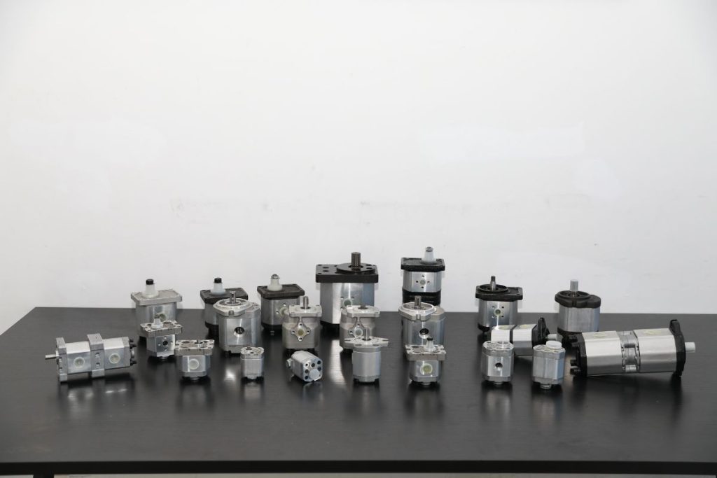
The two groups shown on this page provide different compact-pump selection paths. Compare the available model displacement and installation drawings against the required flow and space. Do not infer universal shaft, flange or pressure compatibility from the group number.
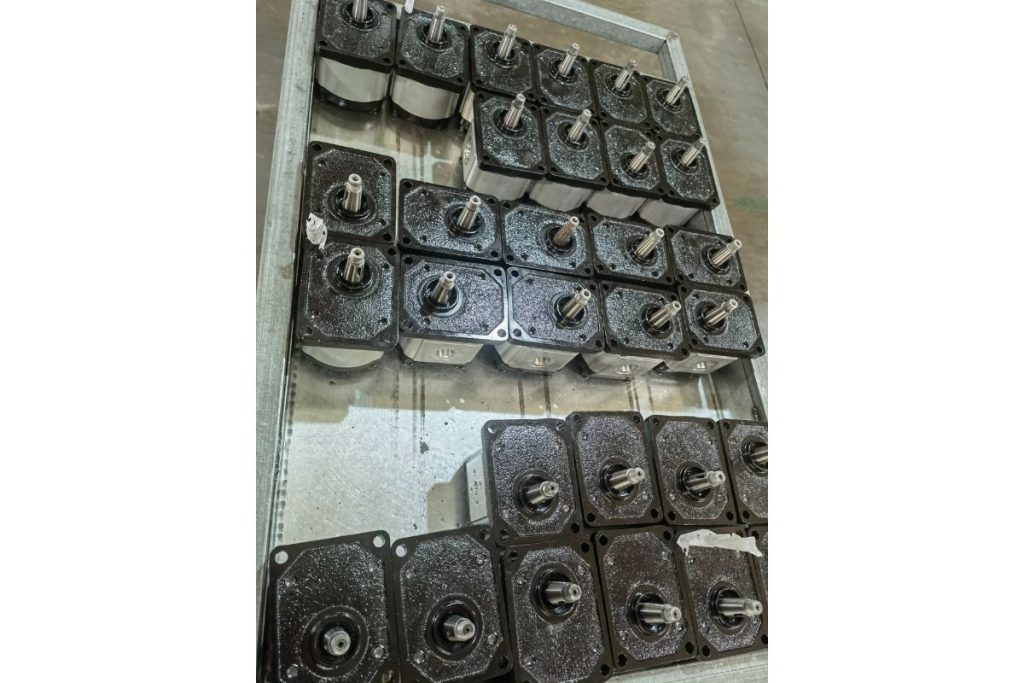
For a small hydraulic power unit, the selected pump also has to fit the motor, manifold and reservoir layout. Check the assembled envelope and service access, not only the pump body dimensions. A photograph of a group example does not replace an interface drawing.
Specify rotation without ambiguity
Write down clockwise or counter-clockwise rotation and state the viewing direction used. Show the intended inlet and outlet in the installation drawing. Confirm that the ordered configuration matches the motor rotation before assembly.
Do not assume a pump can be reversed simply because another member of the same product family is available with the opposite rotation. A CW option and a CCW option are not automatically one bi-rotational model. Any reversal capability must be confirmed for the specific configuration.
Match the shaft, mounting and connections
Provide the motor or coupling drawing when requesting a keyed, splined or other drive interface. Include mounting-hole positions, locating features and the space needed to assemble or remove the pump. The drawing should identify which dimensions are critical to integration.
State the port thread standard rather than only describing a connection as a similar size. Include the intended inlet route, reservoir relationship and outlet connection. These inputs help distinguish an interface match from a visual resemblance.
Use performance and inspection evidence for acceptance
If flow, efficiency or noise is an acceptance requirement, define the test conditions and the pass/fail criterion before release. A useful record identifies the model, speed, pressure, fluid condition and measurement method. A general statement such as “low noise” is not a substitute for a defined requirement.
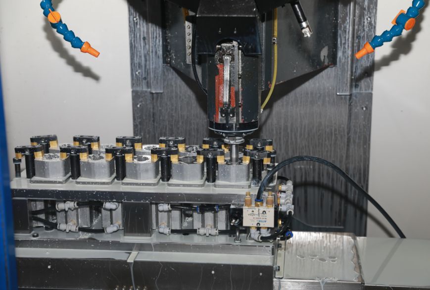
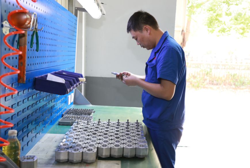
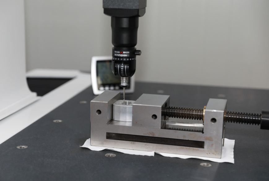
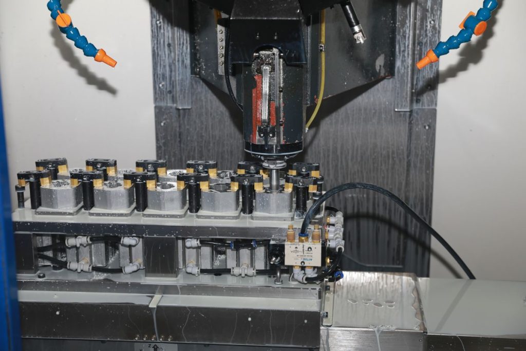
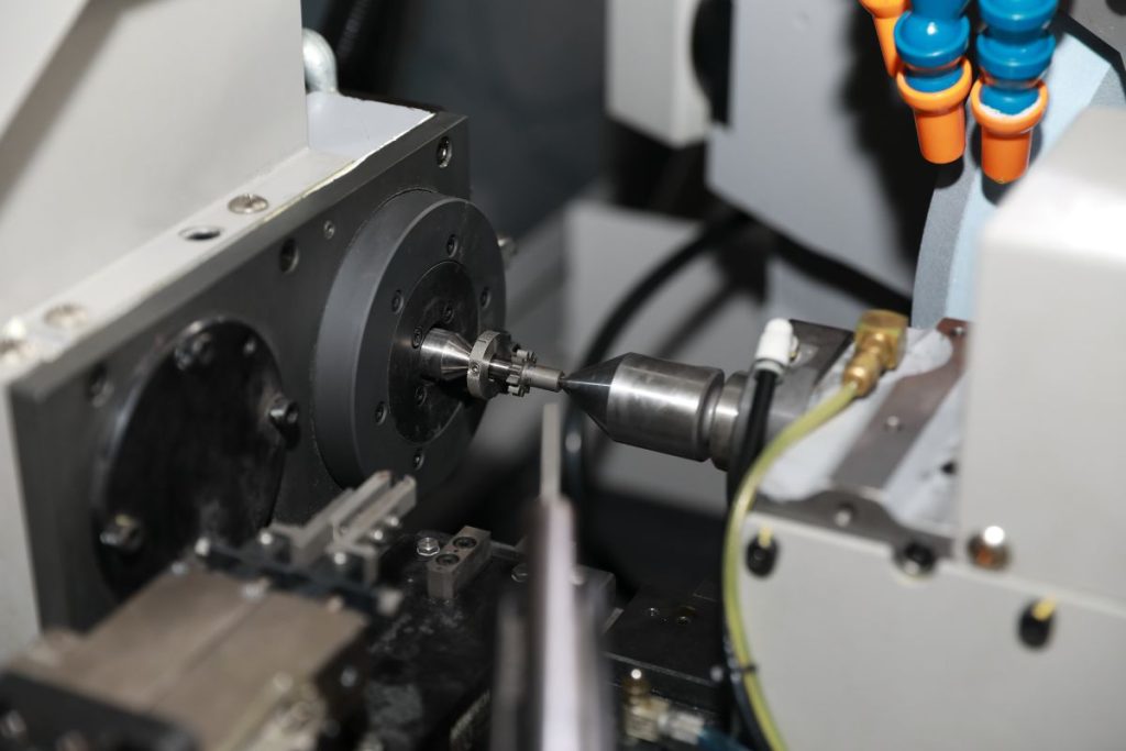
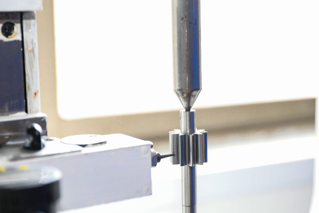
Dimensions, materials, seals and operating limits must be confirmed in the project documentation. Manufacturing photographs and generic examples do not prove a particular tolerance, certification or test result. Request the evidence relevant to your selected configuration.
Send a gear-pump review package
Use the form on this page to send the required flow and pressure, drive-speed range, rotation, fluid conditions and operating cycle. Attach the pump or motor interface drawing and identify any existing part used only as a comparison. Include installation space and the criteria that matter for your machine.
HydrathPower can review these inputs against the gear-pump path shown here. Final supply scope, operating values and interfaces are confirmed for the selected project; no single figure on a family page applies automatically to every configuration.
Existing product photographs and drawings
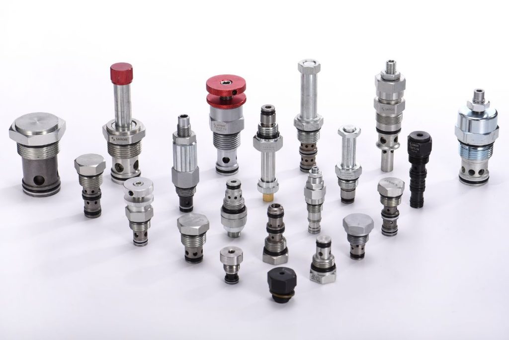
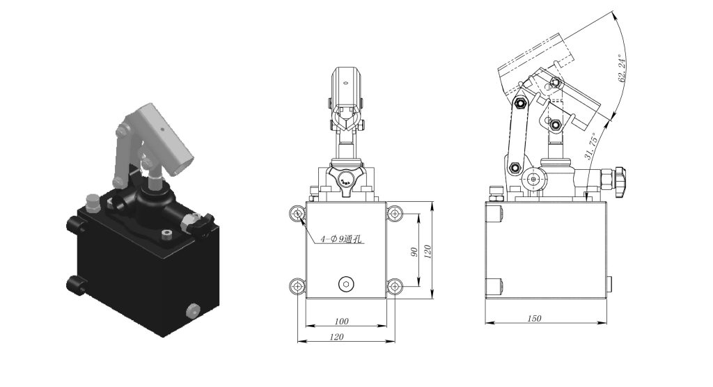
These retained catalogue images show configurations and interfaces. Confirm the exact model and drawing for the enquiry; an image is not a rating, test result or cross-brand compatibility approval.