What is a Hydraulic Gear Pump?
A hydraulic gear pump is a mechanical device that converts mechanical energy into hydraulic energy using two interlocking gears. These positive displacement pumps capture a specific amount of fluid in enclosed chambers and transport it from the inlet to the outlet under pressure.
Hydraulic gear pumps are integral components in modern machinery, powering a wide range of industrial and mobile applications through efficient fluid transfer. Their simple yet effective design provides reliability and ease of maintenance across demanding environments.
Basic Gear Pump Components
The main components of a hydraulic gear pump include:
| Component | Function | Material |
|---|
| Housing | Encloses mechanism, prevents fluid leakage | Cast iron or aluminum alloy |
| Drive Gear | Connected to power source, transfers motion | Steel |
| Driven Gear | Meshes with drive gear, creates displacement | Steel |
| Drive Shaft | Links power source to gears | Steel |
| End Covers | Maintains seal, reduces leakage | Aluminum or steel |

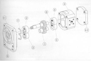 gear pump diagram
The housing encases the entire mechanism for strength while ensuring that no hydraulic fluid escapes the system. The precision tolerances of end covers help reduce leakage while improving volumetric efficiency.
How the Pump Operates in a Hydraulic System
The operation of a hydraulic gear pump involves generating flow through the interaction of gears in the pump cavity:
- Rotation begins: An external power source (engine or electric motor) rotates the drive gear through the drive shaft.
- Suction created: As gear teeth mesh, they create a void that draws fluid from the reservoir into the pump through the inlet port.
- Fluid trapped: The gears trap fluid between their teeth and the inner surface of the housing.
- Transport: The rotating gears carry the trapped fluid along the periphery to the outlet side.
- Discharge: Fluid exits the pump at the outlet port under pressure, ready to power hydraulic actuators or valves.
The amount of pressure created depends on the system load. Gear pumps provide flow, not pressure directly. Pressure develops as resistance to that flow increases in the system.
Understanding Positive Displacement in Pumps
Positive displacement pumps work by capturing and controlling the flow of a specific amount of fluid to ensure a constant rate of movement. This is achieved through mechanical parts like gears, pistons, or diaphragms that create enclosed chambers trapping and moving fluid.
Unlike centrifugal pumps that depend on fluid speed or dynamic pressure, positive displacement pumps offer a constant flow rate regardless of changes in system pressure or fluid viscosity. This property makes them suitable for applications requiring precise fluid measurements.
Comparing Fixed and Variable Displacement Pumps
| Characteristic | Fixed Displacement Pump | Variable Displacement Pump |
|---|
| Flow Rate | Constant per revolution | Adjustable |
| Design Complexity | Simple | Complex |
| Energy Efficiency | Lower in variable load conditions | Higher, responds to demand |
| Cost | Lower | Higher |
| Application | Constant flow systems | Variable load systems |
Gear Pump vs Vane Pump vs Piston Pump Comparison
| Aspect | Gear Pump | Vane Pump | Piston Pump |
|---|
| Operation Principle | Meshing gears | Sliding vanes | Reciprocating pistons |
| Pressure Range | Low to Medium | Medium | High |
| Efficiency | Moderate | Good | High |
| Maintenance | Low | Moderate | High |
| Cost | Low | Moderate | High |
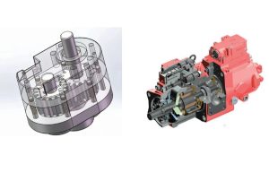 gear pump vs piston pump
Gear pumps are uncomplicated, rugged, and best suited for low-pressure settings. Vane pumps offer more uniform flow with variable stroke control. Piston pumps deliver high efficiency and high pressures, best suited for tasks requiring high accuracy.
Internal Gear Pump Overview
Internal gear pumps differ from external gear pumps in construction and performance characteristics:
- Construction: A larger gear with internal teeth surrounds a smaller inner gear that rotates within it.
- Pressure capacity: Internal gear pumps can support pressures up to 3000 PSI or more.
- Viscosity handling: They excel at handling high-viscosity fluids.
- Temperature range: Many operate between -40 to 400 Fahrenheit depending on construction materials.
- Efficiency: Great volumetric efficiency, ideal for chemical processing, automotive lubes, and hydraulic power units.
- Maintenance: Fewer moving parts result in reduced downtime and extended component life.
Factors Affecting Hydraulic Pump Performance
Fluid Viscosity: Too much viscosity creates excessive resistance leading to inefficiencies and heating. Too little viscosity may not lubricate sufficiently, causing premature component wear.
Temperature Stability: Extreme temperatures affect fluid viscosity and compressibility. Cavitation and pressure losses may arise from thermal issues.
Pump Speed: Rotating too fast can cause volumetric efficiency loss and cavitation. Rotating too slow may not meet system demands.
System Leakages: Both internal and external leaks contribute to pressure loss and increased energy consumption.
Contaminant Control: Particles or water in hydraulic fluid can impede flow and damage components over time.
Frequently Asked Questions
What is a hydraulic gear pump and how does it work?
A hydraulic gear pump converts mechanical energy into hydraulic energy using two interlocking gears. The pump captures fluid between gear teeth and the housing, transporting it from inlet to outlet under pressure.
What pressure can a gear pump handle?
External gear pumps typically operate in the low to medium pressure range (up to 250 bar). Internal gear pumps can handle higher pressures, with some models supporting up to 3000 PSI.
How is pump flow measured?
Pump flow is typically measured in gallons per minute (GPM) or liters per minute (L/min). This measurement indicates how much hydraulic fluid the pump can deliver per minute.
Conclusion
Hydraulic gear pumps are essential components in fluid power systems, offering a balance of simplicity, reliability, and cost-effectiveness. Their positive displacement design ensures consistent flow regardless of pressure changes, making them suitable for a wide range of industrial applications.